Main Control Data
Enter the basic boundary conditions for elements and the analysis conditions for nonlinear elements.
By checking on "Consider Section Stiffness Scale Factor for Stress Calculation" section stiffness variation can be considered for stress calculation.
From the Main Menu select Analysis > Main Control > Main Control Data.
 Auto Rotational DOF Constraint for Truss/Plane Stress/Solid Elements
Automatically constrains the rotational DOF when elements without rotational DOF are used.
 Auto Normal Rotation Constraint for Plane Elements
Automatically constrains the rotational DOF about the axis perpendicular to the plane of a plate element in order to remove unnecessary buckling modes that can occur in a plate element without out-of-plane rotational stiffness. This option is not applicable to a plate element with out-of-plane rotational stiffness.
 Tension/Compression Truss Element (Elastic Link/Inelastic Spring) [Details...]
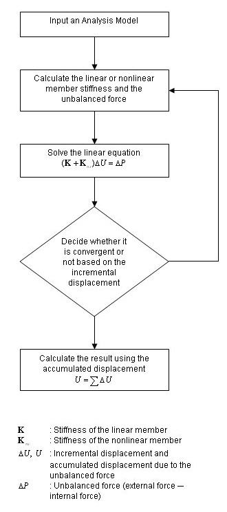
Number of Iterations/Load Case: Enter the maximum number of iterations used to determine the converged condition for each load case.
Convergence Tolerance: Enter the convergence tolerance.
 Consider Section Stiffness Scale Factor for Stress Calculation
Use the section properties reflecting the scale factors, which were defined in Section Stiffness Scale Factor, for stress calculations. Default is checked off.
Note
Select whether or not to consider the increase or decrease in section stiffness for stress calculations. Even if the section stiffness changes, it is common to use the gross section for stress calculations. Thus, the default is checked off.
 Transfer Reactions of Slave Nodes to the Master Node
Transfer reactions of Slave Nodes to the Master Node. Default is checked on.
Note
When this option is checked on, reactions of slave nodes are plotted as zero and total reactions including reactions of slave nodes are plotted in the Summation field of the Reactions Table. When this option is checked off, reactions of slave nodes are plotted in the reaction field of the corresponding slave node.
 Auto Constraint for Wall Elements Connectivity
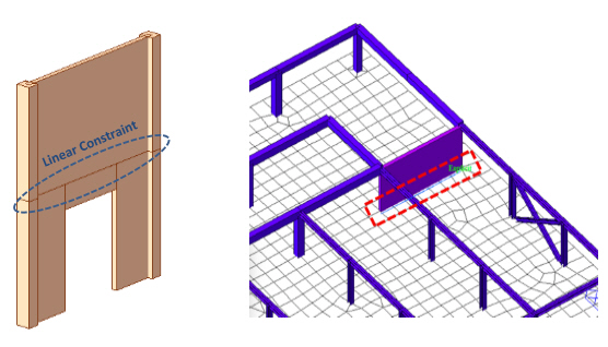
When there are nodes not connected to the wall elements on the top or bottom of wall edges, midas Gen can automatically generates Linear Constraints by checking on this option. DOFs of free nodes are restrained to that of wall nodes.
This option is very useful when wall elements are modeled on the top of meshed plate elements or when Wall Opening is entered.

Generated Position of Linear Constraint
