Story Eccentricity Table
Check or modify the story eccentricities of a building structure in a spreadsheet format table. For eccentricity ratios, Story Center for Eccentricity Ratio must be defined in Building Control Data.
When "Story Shear Force Ratio>Consider Story Module"is checked in the "Model/Building/Control Data", accurate shear forces can be obtained for the story having the overlapping Module.
This function has no relation to Structure > Building > Story > Define Module button.
Table Tool in midas Gen offers a variety of powerful built-in functions. Refer to Usage of Table Tool for detail directions.
From the Main Menu select Results > Tables > Result Tables > Story > Story Eccentricity.
Upon executing the Buckling Mode Shape Table function, Records Activation Dialog prompts. Click ![]() after selecting the output entities such as nodes or elements, loading conditions, construction stages, etc.
after selecting the output entities such as nodes or elements, loading conditions, construction stages, etc.
Note
Refer to Results Table of "Usage of Table Tool" for the usage of Records Activation Dialog.
Refer to Usage of Table Tool and check the following data:
![]() When Modules are not defined
When Modules are not defined
Story: Story ID
Level: Story elevation level
Weight Center: Location of the center of weight
Stiffness Center: Location of stiffness center
Ecc. Dist.: Eccentricity distance
Torsion Stiffness: Torsional stiffness of the story at the stiffness center
El. Radius: Elasticity radius
Ecc. Ratio: Eccentricity ratio
![]() When Modules are defined
When Modules are defined
Module: Module name is defined in Structure > Building > Story > Define Module button
Story: Story ID
Level: Story elevation level
Weight Center: Location of the center of weight
Stiffness Center: Location of stiffness center
Ecc. Dist.: Eccentricity distance
Torsion Stiffness: Torsional stiffness of the story at the stiffness center
El. Radius: Elasticity radius
Ecc. Ratio: Eccentricity ratio
Note
Eccentricity Ratio
(1) Background to Eccentricity Ratio
A lateral seismic load is considered to act through the center of mass in a building plan as shown in Fig. 1. The building structure then undergoes lateral displacements while rotating about the center of the stiffness due to the stiffness eccentricity. If the eccentricity between the centers of mass and stiffness is excessive, displacements at one side of the building may be undesirably large due to the torsion. The eccentricity ratio is defined as the ratio of the eccentricity to the radius of elasticity, which represents torsional resistance. The higher the eccentricity ratio the greater the eccentricity from the stiffness center of the lateral resisting system (frames, bracings, shear walls, etc.) to the mass center.
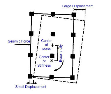
Fig. 1 Building with Eccentricity
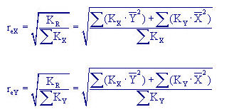
(2) Calculation of Eccentricity Ratio
The eccentricity ratio, Re is considered in each direction at each story. We will simply find the eccentricities at a floor to demonstrate the concept as shown in Fig. 2. The coordinate system does not affect the outcome; so we will locate the origin at the lower left corner here.
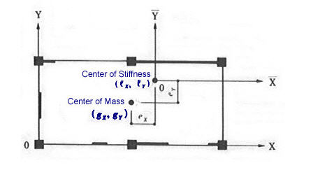
Fig. 2 Torsional notations
Center of mass (weight)
The center of seismic loads at a given floor is the center of the story shear. In order to find the center of the weight at a given floor, we use the axial forces (N) of vertical members (columns, walls, etc.) and their relative locations in X & Y coordinates. If the coordinates of the center is defined as ![]() .
.
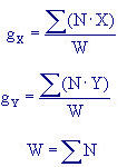
The ∑ represents the summation of all the members resisting the vertical loads. If the gravity loads (dead loads and part of live loads considered to contribute to the seismic loads) are uniformly distributed at each floor, we may assume that the geometric center coincides with the center of mass.
Center of Stiffness
Let us consider individually the lateral stiffness of the lateral load resisting elements such as columns, shear walls and bracings as ![]() and
and ![]() and the coordinates as X and Y. The coordinates of the center of stiffness,
and the coordinates as X and Y. The coordinates of the center of stiffness, ![]() and
and ![]() at each story are obtained as follows:
at each story are obtained as follows:
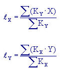
The ∑ represents the summation of the stiffness of all the lateral load resisting elements in the X and Y directions.
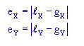
Eccentricities (e)
We can now find the eccentricities using the coordinates of the centers of weight and stiffness.
Torsional Stiffness
Next, we will calculate the torsional stiffness, which is found at each story. Since it is calculated on the basis of the rotation about the center of the stiffness, we will translate the coordinates so that the center of the stiffness becomes the origin. The new coordinate system ![]() now locates the lateral load resisting elements in,
now locates the lateral load resisting elements in,

The stiffness of each lateral load resisting element remains unchanged despite the change of coordinates. The torsional stiffness for the rotation about the center of stiffness, ![]() becomes,
becomes,
![]()
The ∑ represents the summation of the lateral load resisting elements in both X and Y directions.
![]()
![]() represents the radius of elasticity in each of the X and Y directions,
represents the radius of elasticity in each of the X and Y directions, ![]() and
and ![]() ., expressed as follows:
., expressed as follows:
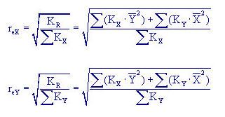
Calculation of ![]()
Using the radii of elasticity obtained above, we can then define the Elasticity Ratios in X and Y directions as ![]() and
and ![]() .
.
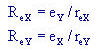
Please exercise caution that the subscripts of the eccentricities ![]() and
and ![]() are in the perpendicular directions to the directions being examined.
are in the perpendicular directions to the directions being examined.
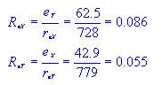
(3) Example calculation
Calculate the Eccentricity Ratios for the structural plan indicated in Fig. 3, which also shows the distribution of shear force coefficients.
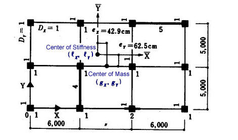
Fig. 3 Structure with eccentricities
Let us define the origin at the lower left corner. The radii of elasticity then become,
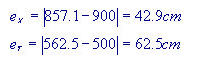
For the sake of simplicity in this case, we assume that the geometric center as the center of weight. In reality, this is generally not the case; it should be determined from the loads in the vertical members. The eccentricity in each direction is as per Fig. 3.
The X-component of the torsional stiffness for the rotation about the center of stiffness is calculated as,
![]()
Similarly, the Y-component is calculated as,
![]()
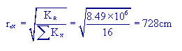
The torsional stiffness for the rotation about the center of stiffness thus becomes,
![]()
The radius of elasticity in the X-direction is,
Similarly,
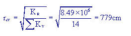
Thus, the eccentricity ratios are now obtained as,