Steel Code Check
Using the analysis results and the specified strength verification data, the member capacities of steel members are examined according to the following Steel Structures Design Criteria:
Load and Resistance Factor Design of the American Institute of Steel Construction (AISC-LRFD93, 2K, 05 & 10 & 16)
Allowable Stress Design of the American Institute of Steel Construction (AISC-ASD89, 05 & 10 & 16)
BS 5950 of the British Standards Institution (BS 5950-90:Part 1. Code of practice for design in simple and continuous construction:hot rolled sections)
Canadian Standard Association (CSA-S16-01)
EN 1993-1-1:2005 Eurocode 3 (Design of Steel Structures; Part 1.1 General Rules and Rules for Buildings)
ENV 1993-1-1:1992 Eurocode 3 (Design of Steel Structures; Part 1.1 General Rules and Rules for Buildings)
Limit States Design of the Canadian Standards Association of Steel Structures (CSA-S16-01, Limit States Design)
Cold-Formed Steel Design of the American Iron and Steel Institute(AISI-CFSD86, Cold-Formed Steel Design).
Architectural Institute of Japan (AIJ-ASD02)
Korean Society of Steel Construction (KSSC-LSD09, KSSC-ASD03)
Architectural Institute of Korea (AIK-ASD83, Allowable Stress Design)
Specifications for Roadway Bridges and Steel Bridges of the Korean Society of Civil Engineers (KSCE-ASD96, Allowable Stress Design)
Steel Structures Limit-State Design Criteria of the Architectural Institute of Korea (AIK-LSD97, Limit-State Design)
Cold-Formed Steel Design of the Architectural Institute of Korea(AIK-CFSD98, Cold-Formed Steel Design)
China Standard (GBJ17-88, GB50017-03)
Indian Standard (IS800-1984, IS800-2007)
Taiwanese Standard (TWN-LSD90 & 96, TWN-ASD90 & 96)
The module verifies strength of overall steel members reflecting live load reduction factors, correction factors for seismic loads and moving loads. It also reanalyzes and reevaluates strength for selected members due to varying design properties and criteria. It provides an optimal section design feature.
The Steel Code Check module performs serviceability checks as per Eurocode 3.
The Steel Code Check module performs strength verification for nonlinear steel members.
Note 1
In cases where tension-only/compression-only elements have extremely
small compressions/tensions, the compression / tension forces
are ignored in the design processes of the members if they are
less than 1/10000 of (Area X Fy).
Note 2
Following section types and shapes are applicable in Steel Code Checking.
Applicable section type: DB/User type, Tapered type
Applicable section shape:
L, C, H, T, Box, Pipe, Rectangle, Round, Double-L and Double-C type for other standards except for AISI-CFSD86
CC (Cold-Formed Channel with Lips) for AISI-CFSD86
Star-battened Angle for Eurocode3:05
Combined tab > I-C Combined Shape for IS:800-2007
From the Main Menu select Design > Design > Steel Design >Steel Code Check.
Shortcut key: [Ctrl] + [6]
Strength verification results are produced by elements or sectional properties coupled with the maximum stress ratios (combined strength ratios) and the corresponding load combinations.
The user selects the unit system for the strength verification results.
9. AIJ-ASD02 (available upon request)
10. AIK-ASD83 (available upon request)
11. KSCE-ASD96 (available upon request)
12. AIK-LSD97 (available upon request)
13. AIK-CFSD98 (available upon request)
14. KSSC-ASD03(available upon request)
15. GBJ17-88(available upon request)
Common Control
![]() :
Display the applicable code for strength verification.
:
Display the applicable code for strength verification.
![]()
Display the strength verification results for the maximum combined stress ratios (combined strength ratios) by elements or properties.
Sorting by Property displays the strength verification results of the element producing the maximum combined stress ratio (combined strength ratio) among the members of the same property.
Once Property is selected, SEL controls all the elements of the same properties.
![]() :
Display the unit system selected by the user.
:
Display the unit system selected by the user.
When the strength verification results that accompany the maximum combined stresses (strength) are to be produced by elements, the results are sorted by section numbers or element numbers in an ascending order.
![]() :
Select all the members
:
Select all the members
![]() : Cancel the selection of all the members
: Cancel the selection of all the members
![]()
Redesign the selected members.
When the redesign is executed from the results displayed by section properties all the elements attributed to the same sections are included.
![]()
Check in the option to select and highlight the selected members in Model View.
![]() :
Display detail strength verification results
:
Display detail strength verification results
![]() :
Display simplified strength verification results
:
Display simplified strength verification results
![]() :
Produce the strength verification results in the form of summary
calculations for the selected members.
:
Produce the strength verification results in the form of summary
calculations for the selected members.
![]() :
Produce the strength verification results in the form of detail
calculations for the selected members.
:
Produce the strength verification results in the form of detail
calculations for the selected members.
![]() :
Produce a summary list of strength verification results for the
selected members.
:
Produce a summary list of strength verification results for the
selected members.
When the results are sorted by properties, the member design results are produced for the member with the maximum combined stress (strength).
![]()
All: Produce all the strength verification results in the Checking Results dialog box
OK: From the strength verification results, display only the design results that have met the design requirements (OK) in the Checking Results dialog box
NG: From the strength verification results, display only the design results that have not satisfied the design requirements (NG) in the Checking Results dialog box
![]()
Produce strength verification results for all the load combinations for the selected members.
![]() :
Close the dialog box
:
Close the dialog box
Section change
![]() :
Propose sections satisfying the selected element conditions.
:
Propose sections satisfying the selected element conditions.
Member Name: Section name internally stored by the program
CHK: Display the strength verification results by sections
= "OK": Stress (required strength) of the section is within the allowable stress range (design strength)
= "NG": Stress (required strength) of the section exceeds the allowable stress range (design strength)
SEL: Select the sections to be changed.
LCB: Load combination number which produces the maximum combined stress ratio (combined strength ratio)
COM: Maximum Combined Stress Ratio (combined strength ratio)
SHR: Stress ratio (strength ratio) for shear force = shear stress/Allowable shear stress (Required shear strength/Design shear
strength)
H: Height of the section
B: Width of the section
Area: Area of the section
![]() :
Select the property number to be changed
:
Select the property number to be changed
![]() :
Open an MGB file to be used as the section DB
:
Open an MGB file to be used as the section DB
(The MGB file containing section data saved by the user can be used ; only DB/User Section is included in the DB construction)
![]() :
Select a DB for the change of sections
:
Select a DB for the change of sections
![]() :
Select a section shape to which the section is to be changed
:
Select a section shape to which the section is to be changed
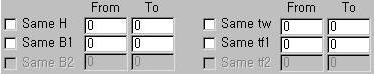
Specify the range of sectional dimensions within which the section is to be changed.
Select the Checkbox if the range of the section dimensions is to be partially identical to the current section in use. To specify the range, enter the dimensions corresponding to the units used in From and To.
Enter the dimensions only in the From fields when the new section is pre-defined with known dimensions.
![]() :
Specify the range of combined stress ratios (combined strength
ratios) for the section to be changed.
:
Specify the range of combined stress ratios (combined strength
ratios) for the section to be changed.
![]() :
Verify strength and produce results for the section satisfying
the design conditions.
:
Verify strength and produce results for the section satisfying
the design conditions.
![]() : Prints all section properties that satisfy the design conditions
in a text format.
: Prints all section properties that satisfy the design conditions
in a text format.
![]() :
Select the sorting preference for section strength verification
results.
:
Select the sorting preference for section strength verification
results.
![]() :
Verify the strength of the selected section, save the changed
results in the steel strength verification file
:
Verify the strength of the selected section, save the changed
results in the steel strength verification file
(.GD1) and close the dialog box.
![]() :
Perform strength verification for the changed section and save
the changed results in the steel strength verification file (.GD1).
:
Perform strength verification for the changed section and save
the changed results in the steel strength verification file (.GD1).
![]() :
Close the dialog box.
:
Close the dialog box.
Update Changed Properties
![]() :
Update the modeling properties with the changed sections after
performing strength verification.
:
Update the modeling properties with the changed sections after
performing strength verification.
Properties Before Change represents the sectional properties used in the analysis.
Properties After Change represents the changed sectional properties subsequent to performing the final strength verification.
![]() :
Auto-select only the changed properties.
:
Auto-select only the changed properties.
![]() :
Cancel all the selections
:
Cancel all the selections
![]() : Update the properties in the model with the selected sections.
: Update the properties in the model with the selected sections.
![]() :
Close the dialog box
:
Close the dialog box
Plot strength verification results in graphs
![]()
Plot the graphs for strength verification results by materials, sections and members.
![]() :
Select all
:
Select all
![]() :
Cancel all the selections
:
Cancel all the selections

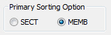
Select the sorting option for graphic output. (Define a table output reference for SEL selection)

Select a graphic output option. (Select Line or Vertical Bar)
![]()
Specify the load combination for graphic output (All signifies the load combination which produces the maximum ratio among all the load combinations)
 :
Select a ratio type for output
:
Select a ratio type for output
![]() :
Enter the ratio range for output
:
Enter the ratio range for output
![]()
Select elements satisfying Sorting Option, Load Combinations for Steel Code Checking, Ratio and Ratio Limit in Model View.
![]()
Check in the box to produce the graph on the existing View. (If unchecked, a new View is selected)
![]()
Produce the strength verification result ratios on a graph for members satisfying the selected conditions
![]() : Close the
dialog box
: Close the
dialog box
![]() Procedure for Serviceability Check as
per Eurocode 3
Procedure for Serviceability Check as
per Eurocode 3
1. Select the design code: Eurocode 3
2. Generate load combinations as per Eurocode2
3. Assign/Confirm Serviceability Load Combination Type
Design > General Design Parameter > Serviceability Load Combination Type
4. Enter Serviceability parameters
Design > Steel Design Parameter > Serviceability Parameters
5. Check Result Dialog: Review the deflection limit checking results in the last column of the Result Dialog.
Design > Steel Code Checking
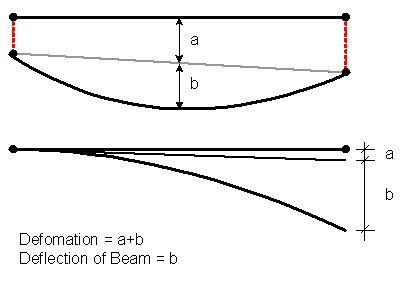
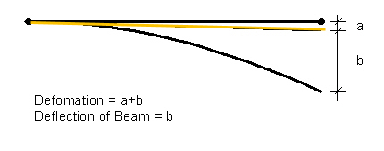
[Notation]
Def |
: Deflection |
Defa |
: Allowable deflection |
6. Check Graphic Results
Serviceability checking results will be produced under the "Deflection Checking Result" at the bottom of the Graphic Report.
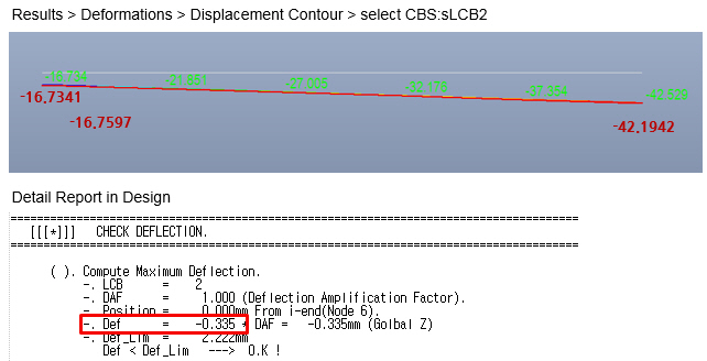
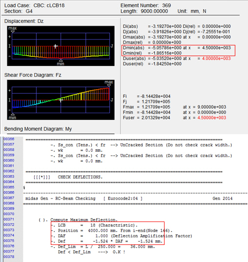
7. Check Detail Results
Serviceability checking results (i.e., deflection checking results) will be produced in the Detail Report.
![]() Revision
of Gen 2015 (v1.1)
Revision
of Gen 2015 (v1.1)
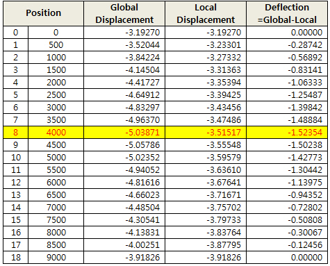
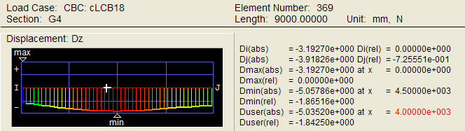
Q1. How midas Gen calculates maximum deflection in a member in Service Limit State Check?