Hysteretic Isolator (MSS)
Add, modify or delete the properties of Hysteretic Isolator (MSS) elements.
From the Main Menu select Boundary > Link > General Link > Seismic Device Properties > Hysteretic Isolator (MSS)
![]() To
enter or add new properties of Hysteretic Isolator (MSS) elements,
click the
To
enter or add new properties of Hysteretic Isolator (MSS) elements,
click the ![]() button.
button.
![]() To
modify the properties of Hysteretic Isolator (MSS) elements already
defined, select a name from the list of Hysteretic Isolator (MSS)
property, click the
To
modify the properties of Hysteretic Isolator (MSS) elements already
defined, select a name from the list of Hysteretic Isolator (MSS)
property, click the ![]() button and
change appropriate data entries.
button and
change appropriate data entries.
![]() To
modify the properties of Hysteretic Isolator (MSS) elements already
defined, select a name from the list of Hysteretic Isolator (MSS)
properties, click the
To
modify the properties of Hysteretic Isolator (MSS) elements already
defined, select a name from the list of Hysteretic Isolator (MSS)
properties, click the ![]() button and
change appropriate data entries.
button and
change appropriate data entries.
 Name
Name
Enter the name of Seismic Device.
 Hysteresis
Properties
Hyst. Model: Select the Hysteretic model of the steel damper.
Initial stiffness (K0): Enter the initial stiffness of the steel damper.
 Yield
Strength
P1: Enter the first yield strength of the steel damper.
P2: Enter the second yield strength of the steel damper.
 Stiffness Factor
α1: Stiffness coefficient after first yielding in compression and tension side. (It is defined as α1 * K0.)
α2: Stiffness coefficient after second yielding in compression and tension side. (It is defined as α2 * K0)
 Hysteresis Parameters
β : Exponent in Unloading stiffness Calculation.
 Multi-shear Spring (Dy-Dz)
n: Input a number of Shear Springs. It is used for considering the direction of seismic load. The more shear springs, the more accurate results can be obtained in various directions.
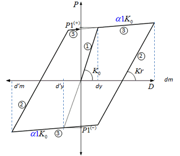
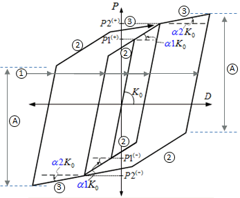
 Drawing of Curve by Hyst. Model

Figure 1. Degrading Bilinear Model |
(1) K1 = K0
(2) K2 = Kr = K0{(dy-d’y)/(dm-d’m)}β dy=d’y, dm=d’m For Steel, β = 0 For Concrete, β = 0.4
(3) K3 = α1*K0
|

Figure 2. Normal Trilinear Model |
(1) K1 = K0
(3) K3 = α2*K0
(A) (+)P1 + (-)P1
|