Panel Zone Effects
Automatically consider the stiffness effects of the Panel Zone where column members and girder members (horizontal elements connected to columns) of steel structures are connected. Panel Zone Effects are reflected in the beam elements. Column members are recognized as beam elements parallel to the GCS Z-axis and beam members are recognized as beam elements on the GCS X-Y plane.
From the Main Menu select Boundary > Etc. > Panel Zone Effects.
 Auto Calculate Panel
Zone Offset Distances
Auto Calculate Panel
Zone Offset Distances
Auto-calculate the panel zone based on the dimensions of the members and take them into account for stiffness calculations.
Offset Factor: Effective factor for the offset distances in panel zones
Output Position: Output position of element's internal forces
Panel Zone: Output of element's internal forces at the Panel Zone boundaries
Offset Position: Output of element's internal forces at the positions adjusted by the Offset Factor
Do not Calculate
Do not consider the panel zones.
Note
Using Panel Zone Effects, if Output Position = Offset Position,
the elements' stiffness, self-weights, distributed loads and output
positions of the member
forces depend on the panel zones adjusted by the offset factor.
In addition, if Output Position = Panel Zone, only the elements'
stiffness are adjusted depending on the offset factor similar
to the case where Output Position = Offset Position. Application
of self-weights/distributed loads and the output positions of
the member forces are fixed to the Panel Zone boundaries (faces
of the columns for girders and top/bottom flanges of the girders
for columns).
For reference, in Panel Zone Effects, the case where Output Position = Offset Position and Offset Factor = 1.0 produces the same condition as in the case where Output Position = Panel Zone and Offset Factor = 1.0. Output Position = Offset Position and Offset Factor = 0.0 produce the same conditions as if the Panel Zone Effects are not considered at all.
When the panel zones are auto-calculated using Panel Zone Effects, the method of applying self-weights and distributed loads or the output positions of the member forces are determined according to the specified Output Position.
Calculation of element stiffness
The distance between the end nodes of an element is used to calculate the axial stiffness and the torsional stiffness. The distance reflecting the offset factor (L1 = L - ZF (Ri + Rj )) is used to calculate the shear stiffness and the bending stiffness regardless of the specified Output Position. Where, L is the length between the end nodes of the element.
Calculation of distributed load
If Output Position = Panel Zone, the distributed loads applied to the section between the extremities of panel zones and the nodes are considered only as shear forces at the relevant nodes. The distributed loads applied to the remaining section are converted into appropriate shear forces and moments.
When Output Position = Offset Position, the positions adjusted by the Offset Factor are used.
Considered length for self-weight
The self-weights of column members are considered for the full distances between the end nodes irrespective of the use of Panel Zone Effects. For girder members, when Output Position = Panel Zone, the net distances excluding the panel zones (L1 = L - (Ri + Rj )) are used to calculate the self-weights. When Output Position = Offset Position, the offset distances reduced by the offset factor (L1 = L - ZF (Ri + Rj )) are used. In addition, the defined self-weights are considered in the analysis by converting into shear forces and moments similar to that for the distributed loads described above.
Output positions of member forces
If Output Position=Panel Zone, the member forces for columns and girders are additionally produced at the quarter points of the net lengths between the Panel Zones.
When Output Position = Offset Position in the case of girder members, the member forces at the quarter points are based on the member lengths adjusted by the offset factor. For example, Output Position = Panel Zone corresponds to the case where Output Position = Offset Position and Offset Factor =1.0. The member forces at these positions are also used in the Design functions.
Panel zone considering Beam End Release Condition
Panel Zone Effect are not considered at the points of beam end releases. (Refer to "Beam End Release")
Method of considering offset distances for each member type using Panel Zone Effects
The panel zones for each member type is considered by the following methods :
Column members
The length of a column member is the floor to floor height.
midas Gen assumes that the top flanges of beam members correspond to the story level. As such, the panel zones for column members need to be considered only at the tops of columns. (Refer to "Structure Type")
The panel zones for column members are determined by the directions and depths of the girder members connected to the column members. The panel zones for column members are separately calculated for moments about local y and z-directions.
When girder members are connected to a column in several directions, the panel zones for each direction are calculated by the following methods (Fig.1):
RCy = BD x cos2![]()
RCz = BD x sin2![]()
RCy: Panel zone for moment about the element's local y-axis at the top of a column member
RCz: Panel zone for moment about the element's local z-axis at the top of column member
BD: Depths of girder members connected to the column member
![]() :
Angle formed by the girder member and the local z-axis of the
column member
:
Angle formed by the girder member and the local z-axis of the
column member
The Panel zones for a column member in each direction are determined by the largest values among the panel zones in the directions of the girder members.
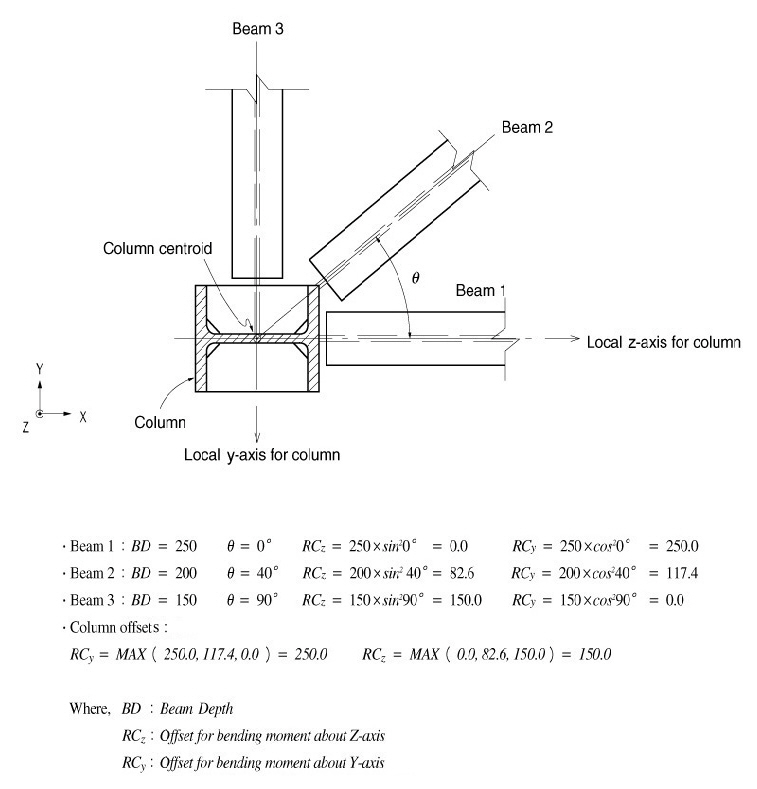
Figure 1 Example of calculation of column panel zones
Girder members
The panel zones for girder members are determined by the Depth and Width of the column members at both ends. The calculation method is described below.
- Equation for panel zone distance (Fig.2)
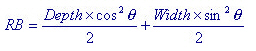
Depth: Section dimension of the column member in the element's local z-direction
Width: Section dimension of the column member in the element's local y-direction
![]() :
Angle formed by the girder member and the element's local z-axis
of the column member
:
Angle formed by the girder member and the element's local z-axis
of the column member
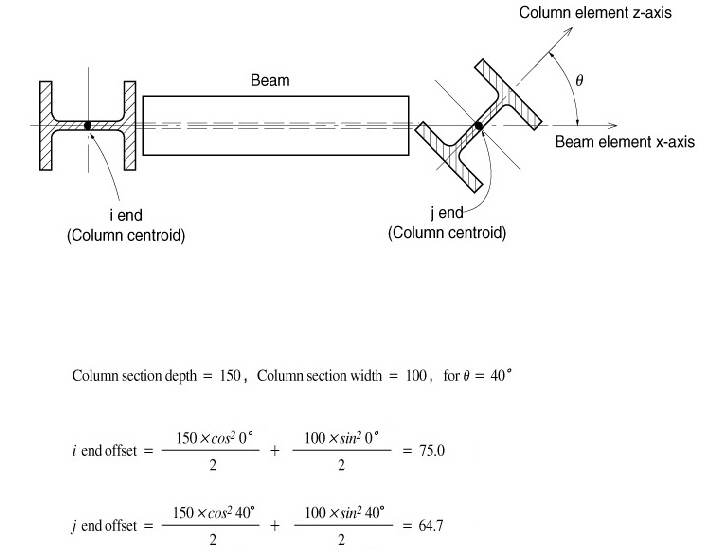
Figure 2 Example of calculation of girder member panel zones