Design Code
Determine the design code and the special provisions for seismic design (if required) to perform the design or the strength verification for RC members according to the following Concrete Design Criteria:
EN 1992-1-1:1994 Eurocode2, Design of concrete structures Part 1 (Eurocode2:04)
ENV 1992-1-1:1992 Eurocode2, Design of concrete structures Part 1 (Eurocode2)
Ultimate Strength Design, the American Concrete Institute (ACI318-14/11/08/05/02/99/95/89)
Colombian Earthquake Resistance Building Code Ultimate Strength Design (NSR-10)
Canadian Standards Association of Concrete Structures (CSA-A23.3-94)
British Standard, Structural use of concrete Part 1 (BS8110-97)
Taiwanese Standard (TWN-USD100/92)
Indian Standard (IS456:2000)
Architectural Institute of Japan (AIJ-WSD99)
China Standard (GB50010-10/02)
Architectural Institute of Korea (AIK-USD94)
Korean Society of Civil Engineers (KSCE-USD96)
Korean Concrete Institute (KCI-USD12/07/03/99)
Architectural Institute of Korea (AIK-WSD2K)
Note 1
If the user omits the design code, the Concrete Structure Design Code of the European Standard (Eurocode2:04) is applied by default.
Note 2
Following section types and shapes are applicable in Steel Code Checking.
Applicable section type: DB/User type
Applicable section shape for Beam: Solid Rectangle, T-Section
Applicable section shape for Column: Solid Rectangle, Solid Round, Pipe
From the Main Menu select Design > Design > RC Design > Design Code
[When Eurocode2:04 is selected]
 Design Code
RC design code.
National Annex
National Annex for Eurocode2:04.
Note. Available National Annexes are as follows:
Recommended
Italy
Sweden
Singapore
![]() Apply
NTC
Apply
NTC
NTC2008
Option to apply the capacity design rule as per NTC2008
NTC2012
Option to apply the capacity design rule as per NTC2012
NTC2018
Option to apply the capacity design rule as per NTC2018
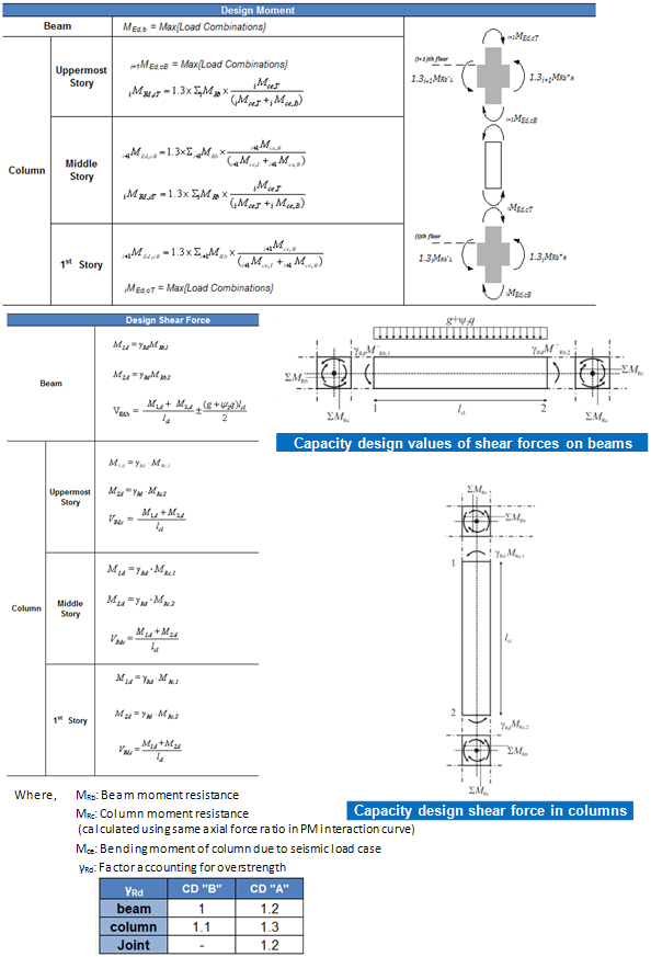
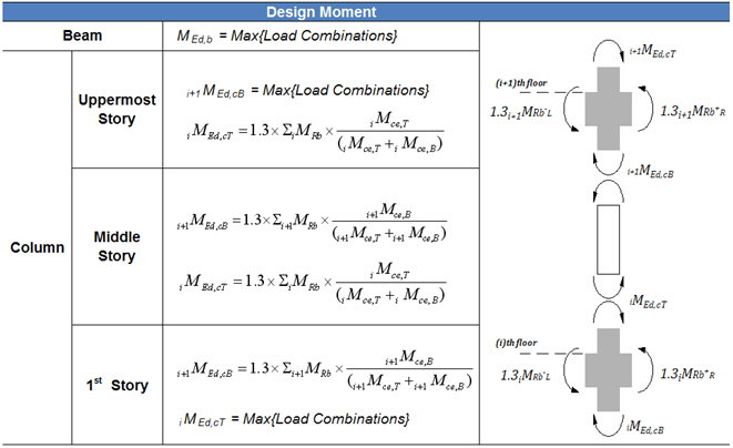
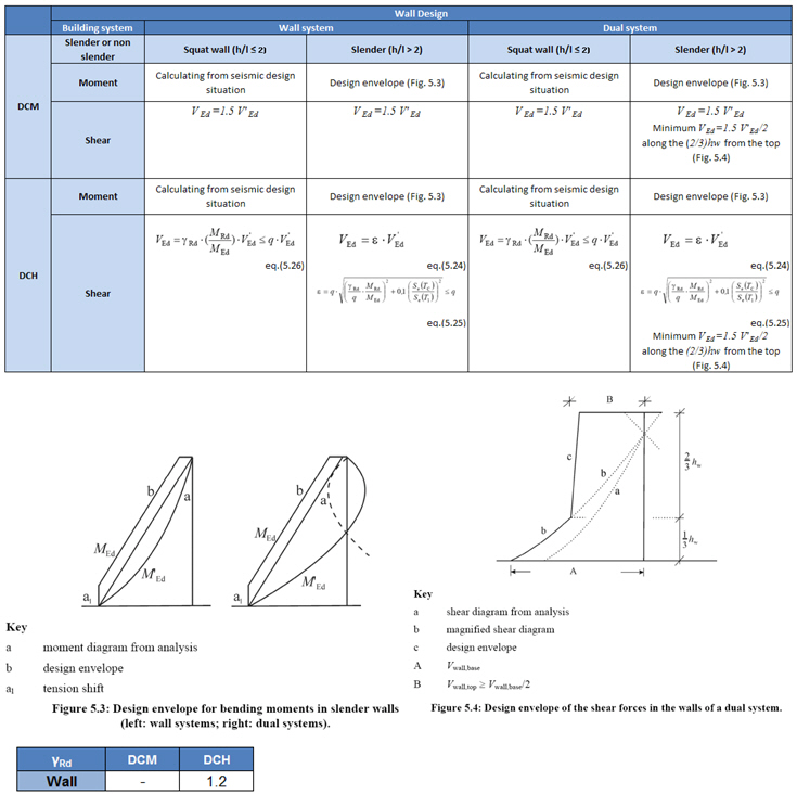
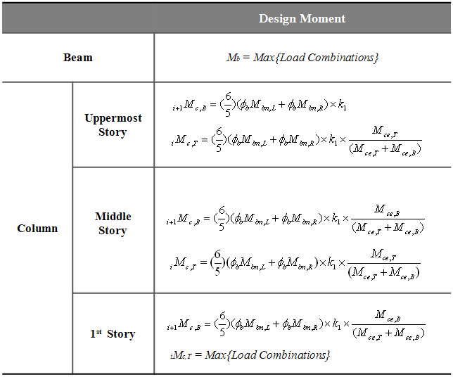
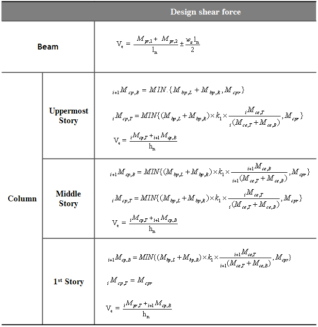
Note. How to calculate design forces of capacity design as per NTC
![]() Apply
Special Provisions for Seismic Design
Apply
Special Provisions for Seismic Design
Option to apply the capacity design rule as per EN1998-1:2004
Note. How to calculate design forces of capacity design as per EN1998-1:2004
![]() Strut Angle for Shear Resistance
Strut Angle for Shear Resistance
The angle between the concrete compression strut and the beam axis perpendicular to the shear force
![]() Slenderness
Limit
Slenderness
Limit
![]() (5.13N)
in EN1992-1-1:2004
(5.13N)
in EN1992-1-1:2004
![]() (Default
value is '0.7'.)
(Default
value is '0.7'.)
![]() (Default
value is '1.1'.)
(Default
value is '1.1'.)
![]() (Default
setting is 'Calculate by Program'.)
(Default
setting is 'Calculate by Program'.)
![]() Strong
Column Weak Beam
Strong
Column Weak Beam
Define the ratio to satisfy the ductility condition at all the joints. Default value is '1.3'.
![]() eq. (4.9)
in EN1998-1:2004
eq. (4.9)
in EN1998-1:2004
![]() Select Ductility Class
Select Ductility Class
For EC8:04
DCH: High ductility level
DCM: Medium ductility level
For NTC2018
CD "A": High ductility level
CD "B": Medium ductility level
Non-Dissipative : Low ductility level
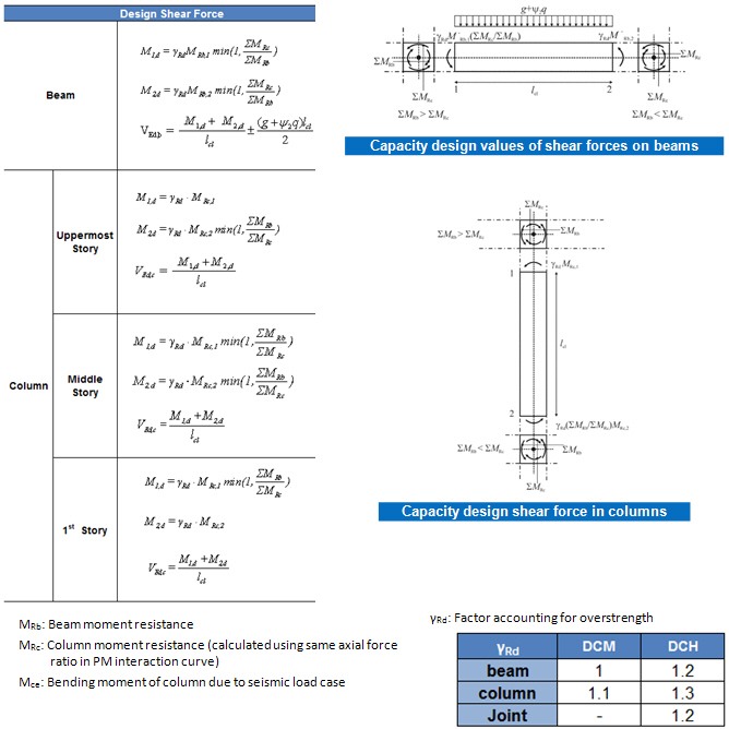
![]() Shear Force for Design (Gamma_rd)
Shear Force for Design (Gamma_rd)
Define the factor accounting for possible overstrength due to steel strain hardening
Default value is as follows:
|
|
Beam |
Column |
Wall |
Joint |
EC8-1:2004 |
DCM |
1 |
1.1 |
- |
- |
DCH |
1.2 |
1.3 |
1.2 |
1.2 |
|
NTC2008 |
CD"B" |
1 |
1.1 |
- |
- |
CD"A" |
1.2 |
1.3 |
1.2 |
1.2 |
|
NTC2012 |
CD"B" |
1 |
1.1 |
- |
1.1 |
CD"A" |
1.2 |
1.3 |
1.2 |
1.2 |
|
NTC2018 |
Non-Dissipative |
1 |
1.1 |
- |
1.1 |
CD"B" |
1 |
1.1 |
- |
1.1 |
|
CD"A" |
1.2 |
1.3 |
1.2 |
1.2 |
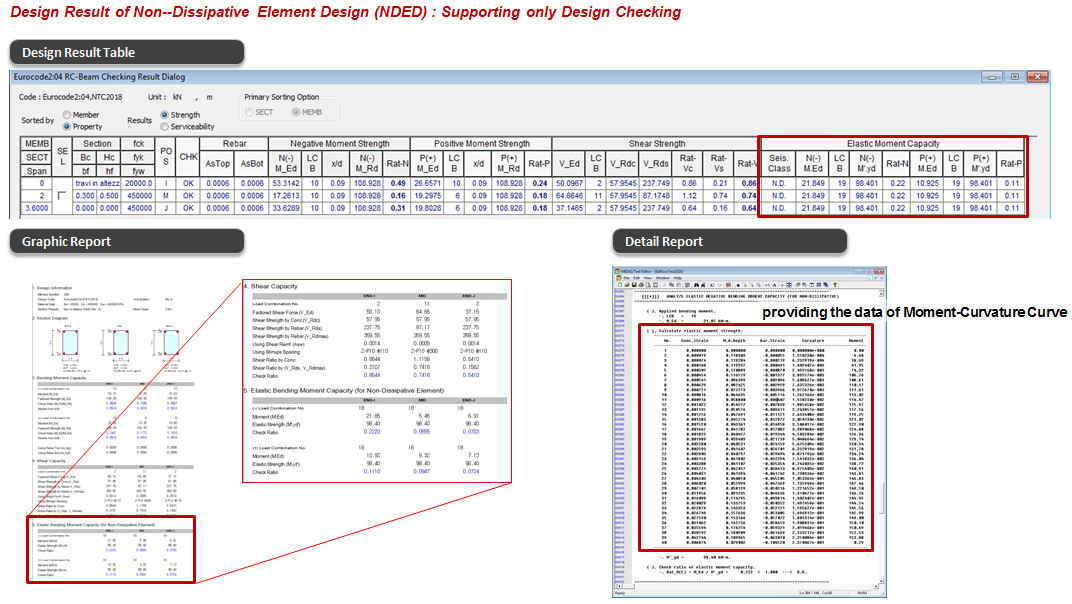
![]() Non-Dissipative
Element
Non-Dissipative
Element
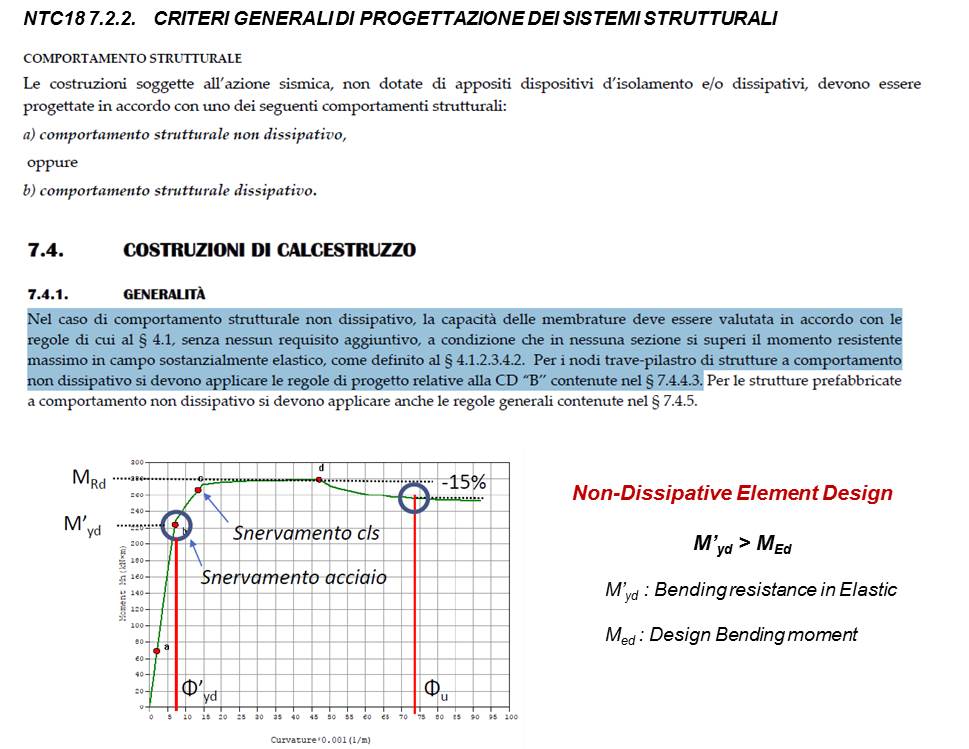
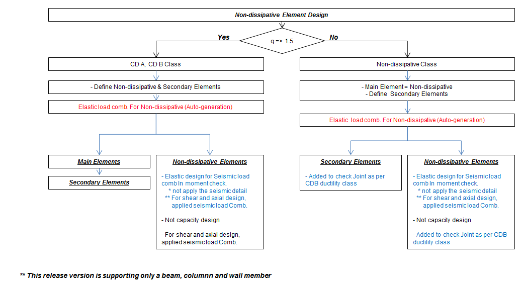
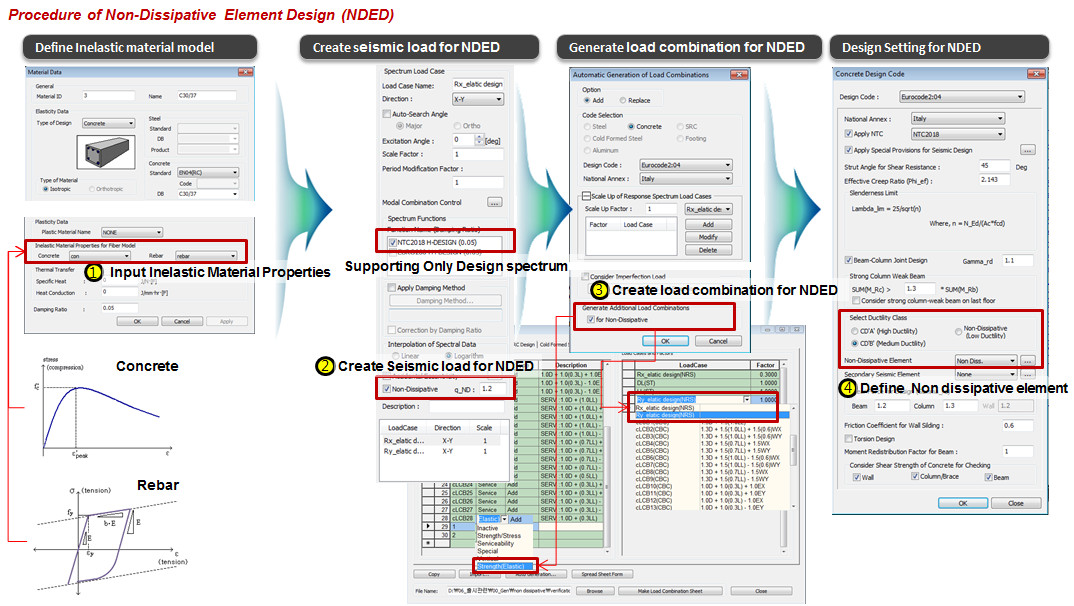
Define the Non-dissipative elements in order to carry out the elastic design
* What is Non-dissipative elements design as per NTC 2018
![]() Secondary Seismic Element
Secondary Seismic Element
Define the secondary seismic elements in order to preclude the capacity design rule
![]() Structure Information
Structure Information
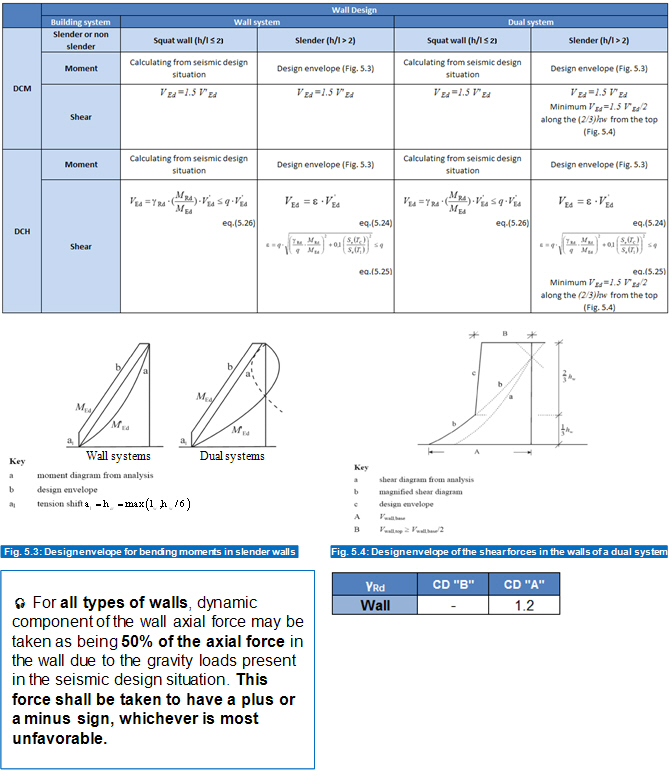
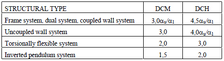
Structure Type: Define structure type to calculate behavior factor and determine the wall design method
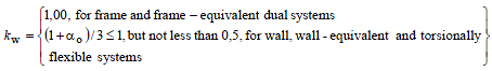
Behavior Factor (q): Behavior factor to account for energy dissipation capacity shall be derived for each design direction as follows:
Calculate by Program: Behavior factor is automatically calculated and applied to the capacity design.
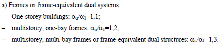
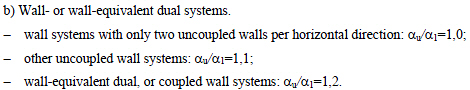
Alpha u / Alpha 1: The multiplication factor for buildings which are regular in plan.
User Input: Behavior factor is directly entered by the user.
Note. Behavior factor for horizontal seismic actions
![]() Elastic Response Spectrum
Elastic Response Spectrum
Default By Function: Select response spectrum function defined in Response Spectrum Function. The spectrums of 'Eurocode8' and 'User Type' are available.
Spectrum Parameters
Soil Factor (S)
Tb: The lower limit of the period of the constant spectral acceleration branch
Tc : The upper limit of the period of the constant spectral acceleration branch
Td: The value defining the beginning of the constant displacement response range of the spectrum
Ref. Reak Ground Acc. (AgR): The design ground acceleration on type A ground
Importance Factor (I)
Viscous Damping Ratio (xi)
![]() Friction Coefficient for Wall Sliding
Friction Coefficient for Wall Sliding
Define the concrete-to-concrete friction coefficient under cyclic actions, which may be assumed equal to 0.6 for smooth interfaces and to 0.7 for rough ones. The default value is 0.7.
![]() Torsion Design
Torsion Design
Check to consider torsion in design.
![]() Consider Shear Strength of Concrete
for Checking
Consider Shear Strength of Concrete
for Checking
Ignore the shear strength of concrete in the calculation of shear resistance for the walls and columns. By checking off this option, the shear resistance of members will be determined by shear reinforcement regardless of the amount of shear strength of concrete. This option works with the Concrete Code Check function.
[When ACI318-08/11/14 is selected]
Design Code
RC design code (refer to Note 1)
Check Beam Deflection
(only ACI318-14 / ACI318M-14)
Options for calculation and evaluation of short/long-term deflection of beam
Apply Special Provisions for Seismic Design
Option to apply the special provisions for seismic design
Select Frame Type
Select the type of frame for seismic zone.
Special Moment Frames: Moment frame in strong-motion seismic zone
Intermediate Moment Frames: Moment frame in intermediate-motion seismic zone
Ordinary Moment Frames: Moment frame in weak-motion seismic zone
Shear Wall Type
Option to apply special structural walls. Select the condition as per Boundary Element Method.
Note : Boundary Element Methods are provided as per clause 21.9.6.2 and clause 21.9.6.3 of ACI 318-08 .
Shear for Design
Apply Scale up Factor for Shear as per special provisions for seismic design.
![]() :
Apply Scale up Factor for Shear as per a relevant code.
:
Apply Scale up Factor for Shear as per a relevant code.
R*Vc(a1*SUM(Mpr)/L>max(Ve1,Ve2)/2)
R: ACI318-05 Clause 21.3.4.2 indicates that " Transverse reinforcement shall be proportioned to resist shear assuming Vc=o when ...". In midas, even though such conditions occur, the user can include a part of shear strength of concrete as well as shear reinforcement.
Method: Select a method to apply Scale up Factor for Shear.
Max(Ve1, Ve2): Use the larger of the shear forces to which Scale up Factors for Shear (a1, a2) will have been applied.
Min(Ve 1, Ve 2): Use the lesser of the shear forces to which Scale up Factors for Shear (a1, a2) will have been applied.
Ve 1: Select to apply Scale up Factor for Shear (a1).
Ve 2: Select to apply Scale up Factor for Shear (a2).
Member Types to be
excluded in Seismic Design :
Select the member types for which Seismic Design is to be excluded .We can also select individual members from Seismic Design Type.
![]() :
Enter the selection and close the dialog box.
:
Enter the selection and close the dialog box.
![]() :
Do not enter the selection and close the dialog box.
:
Do not enter the selection and close the dialog box.
[When ACI318-05 is selected]
Design Code
RC design code (refer to Note 1)
Apply Special Provisions for Seismic Design
Option to apply the special provisions for seismic design
![]() :
Enter the selection and close the dialog box.
:
Enter the selection and close the dialog box.
![]() :
Do not enter the selection and close the dialog box.
:
Do not enter the selection and close the dialog box.
Select Frame Type
Apply different Scale up Factor for Shear for each seismic zone (This is applicable for ACI318-89, 95, 99, 02,05).
Special Moment Frames: Moment frame in strong-motion seismic zone
Intermediate Moment Frames: Moment frame in intermediate-motion seismic zone
Ordinary Moment Frames: Moment frame in weak-motion seismic zone
Shear for Design
Apply Scale up Factor for Shear as per special provisions for seismic design.
![]() :
Apply Scale up Factor for Shear as per a relevant code.
:
Apply Scale up Factor for Shear as per a relevant code.
R*Vc(a1*SUM(Mpr)/L>max(Ve1,Ve2)/2)
R: ACI318-05 Clause 21.3.4.2 indicates that " Transverse reinforcement shall be proportioned to resist shear assuming Vc=o when ...". In midas, even though such conditions occur, the user can include a part of shear strength of concrete as well as shear reinforcement.
Method: Select a method to apply Scale up Factor for Shear.
Max(Ve1, Ve2): Use the larger of the shear forces to which Scale up Factors for Shear (a1, a2) will have been applied.
Min(Ve 1, Ve 2): Use the lesser of the shear forces to which Scale up Factors for Shear (a1, a2) will have been applied.
Ve 1: Select to apply Scale up Factor for Shear (a1).
Ve 2: Select to apply Scale up Factor for Shear (a2).
[When TWN-USD100 is selected]
Apply Special Provision
for Seismic Design
Option to apply the special provision for seismic design.
Shear for Design
Apply Scale up Factor for Shear as per special provisions for seismic design.
![]() :
Apply Scale up Factor for Shear as per a relevant code.
:
Apply Scale up Factor for Shear as per a relevant code.
R*Vc(a1*SUM(Mpr)/L>max(Ve1,Ve2)/2)
R: ACI318-05 Clause 21.3.4.2 indicates that " Transverse reinforcement shall be proportioned to resist shear assuming Vc=o when ...". In midas, even though such conditions occur, the user can include a part of shear strength of concrete as well as shear reinforcement.
Method: Select a method to apply Scale up Factor for Shear.
Max(Ve1, Ve2): Use the larger of the shear forces to which Scale up Factors for Shear (a1, a2) will have been applied.
Min(Ve 1, Ve 2): Use the lesser of the shear forces to which Scale up Factors for Shear (a1, a2) will have been applied.
Ve 1: Select to apply Scale up Factor for Shear (a1).
Ve 2: Select to apply Scale up Factor for Shear (a2).
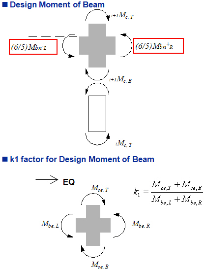
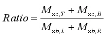
SCWB Design/Checking
Method
Option for design force calculation special provision for seismic design.
Design Strength: Perform strong
column-weak beam design and checking using the design strength
of beams (![]() ).
).
[Ductile Design & Checking calculation]
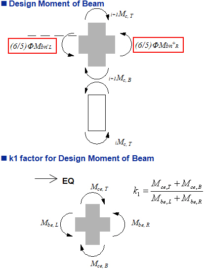
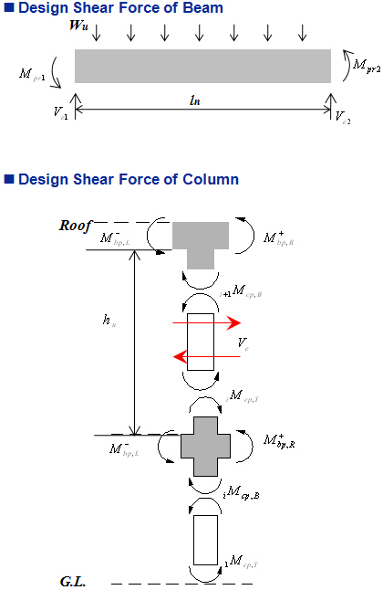
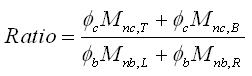
[Strong Column Weak Beam Ratio Calculation]
Nominal Strength: Perform strong
column-weak beam design and checking using the nominal strength
of beams (![]() ).
).
[Ductile Design & Checking calculation]
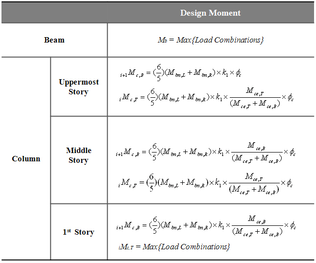
[Strong Column Weak Beam Ratio Calculation]
Torsion Design
Apply torsional design. This option is applicable for TWN-USD100/92 & IS456:2000 only.