|
 Revision of Gen 2015 (v2.1) Revision of Gen 2015 (v2.1)
[July 13, 2015]
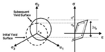
Model > Properties > Plastic Materials
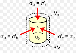
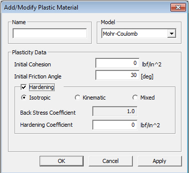
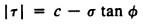
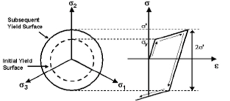
Q1. How can you simulate nonlinear behavior of concrete with plate / solid elements ?
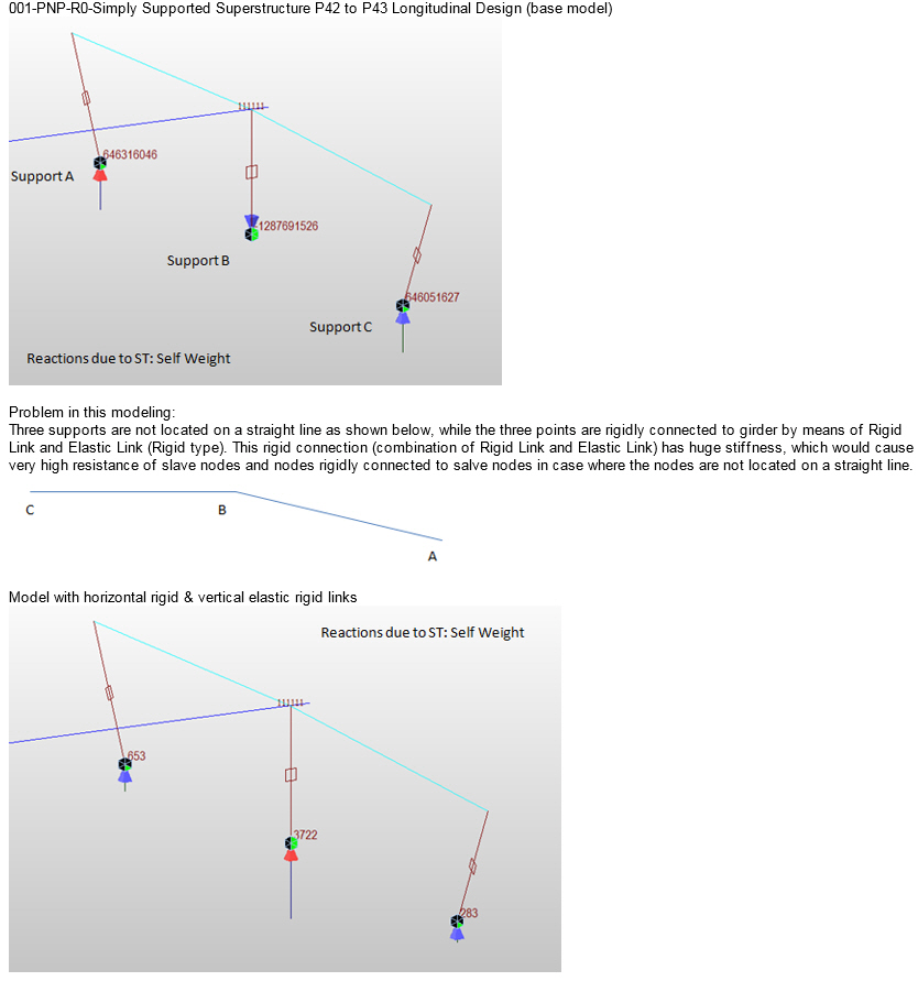
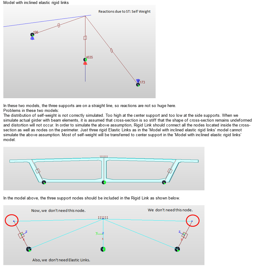
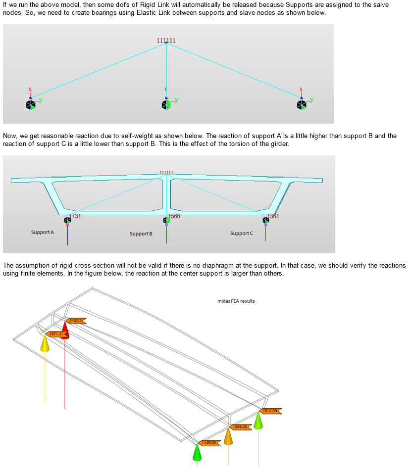
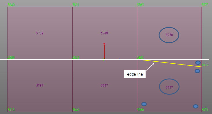
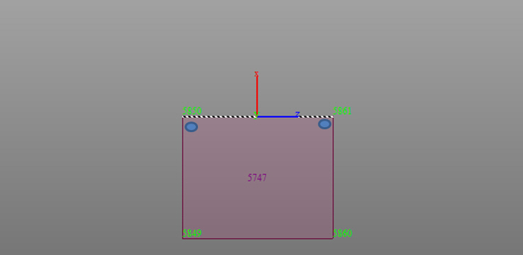
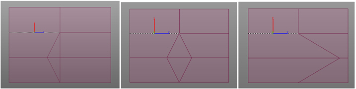
Model > Boundaries > Rigid Link
Q1. If the horizontal and vertical link assembly is changed to inclined link assembly, the vertical reactions change. Why ?
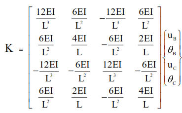
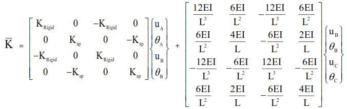
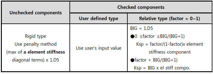
Model > Boundaries > Beam End Release
Q1.Why member force with partial fixity is different from the value of "original member force x scale force"?
Load > Specified Displacements of Supports
Q1. Can you explain why the sum of reactions due to the ‘Specified Displacement’ load case in model file is not equal to zero. It is close to zero but not exactly. Does midas have any setting where the precision can be controlled by the user?
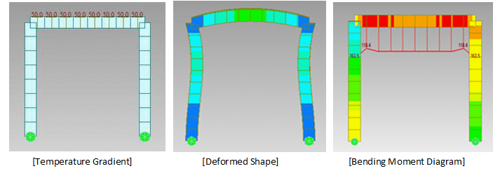
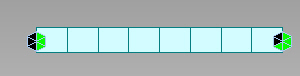
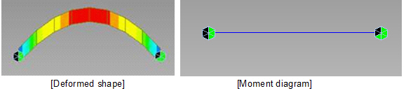
Load > Temp./Prestress > Temperature Gradient
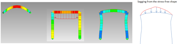
Q1. I applied the Temperature Gradient load of 50 °C (25 °C at the top and -25 °C at the bottom, linear variation in between) to the horizontal member and got the deformed shape of horizontal member in hogging (upwards). I would like to know why the bending moment diagram is sagging (downwards), while the member is deflected in hogging (upwards).
Load > Temp./Prestress > Beam Section Temperature
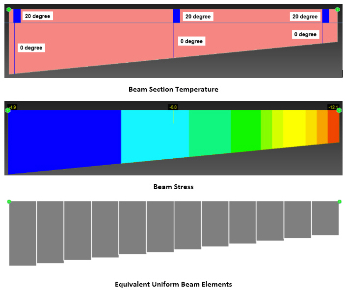
Q1. How Beam Section Temperature load should be applied for tapered section as we cannot define different temperature variation for i-end, middle, and j-end separately?
Load > Temp./Prestress > Tendon Property
Q1. What are the considerations in the program regarding external tendons?
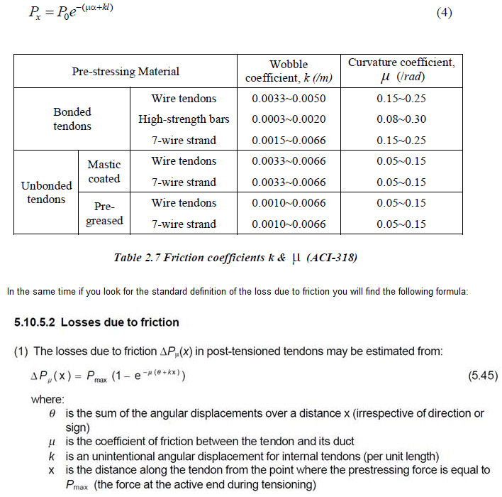
Q2. What is the Wobble Friction Factor and how does it relate to the "unintentional angular displacement"-factor (k)?
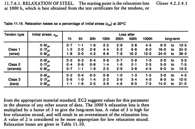
Q3. What is the consideration in the software for relaxation loss calculation when Eurocode is selected?
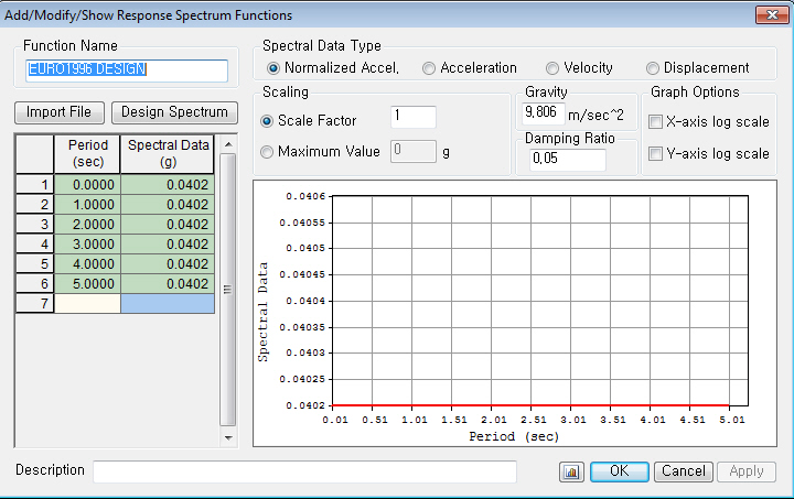
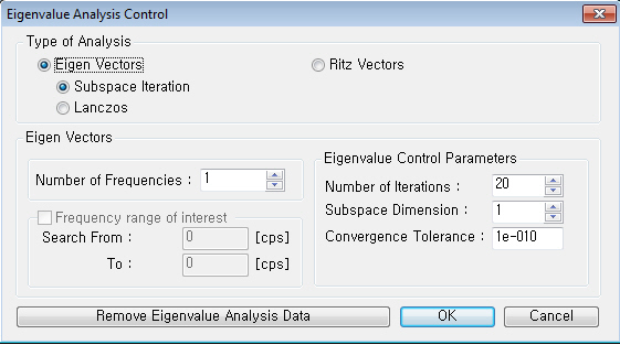
Load > Dynamic Load > Response Spectrum Load Cases
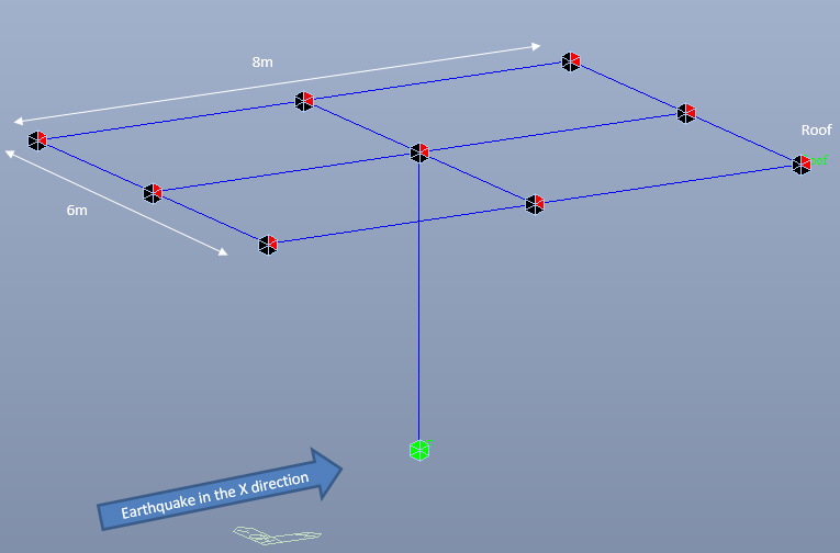
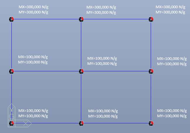
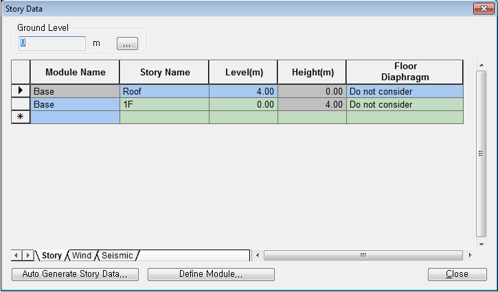
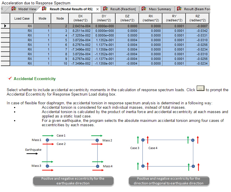
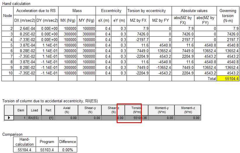
Q1. How midas Gen calculates Accidental Eccentricity when Floor Diaphram is not considered?
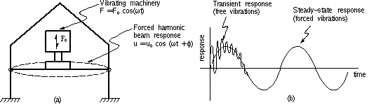
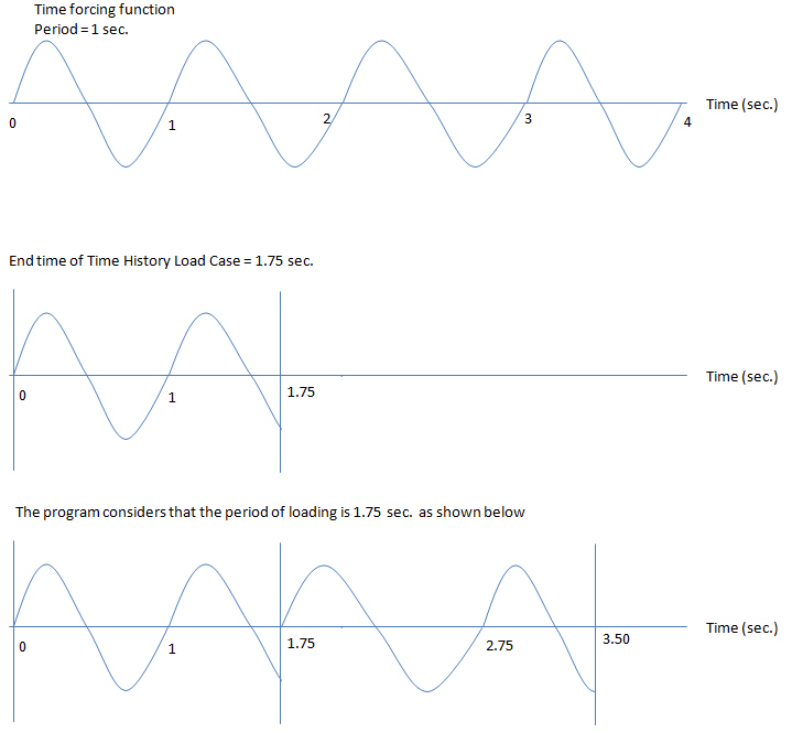
Load > Dynamic Load > Time History Load Case
Q1. Just to illustrate the question I had on periodic TH load case. I am looking at TH load case #3 using the crowd loading. The load has a frequency of 2.98Hz, so a period of t=0.33557s. I have specified End Time as 13.4 seconds (which has remained from the time it takes for the walking pedestrian to cross the bridge, but is irrelevant for the crowd). When I look at Displacement Contour for THmax: Crowd, the max value is 2.82. If I change the End Time of the load case to the period of the forcing function (0.33557), the result comes out as 2.6: Which one is correct? Or am I reading something wrong? From the online manual it sounds as if the correct definition is 0.33557, but then the result is lower than the full time, which is not on the safe side.
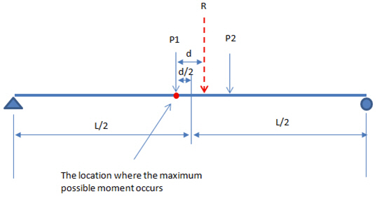
Load > Moving Loads > Define Moving Load Case
Q1. Two wheel loads with the same amount of loading passes along the simple span. After performing moving load analysis, the result of bending moment shows that the maximum bending moment does not occur at the center of span. I do not understand why?
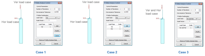
Analysis > P-Delta Analysis Control
Q1. Which load cases do I have to add in “P-Delta Combination”? The result of the load combination which doesn’t include vertical load case was changed after performing P-delta analysis.
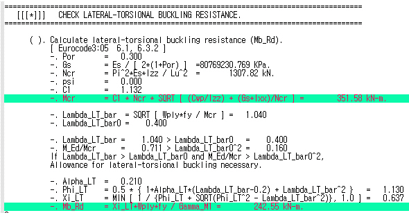
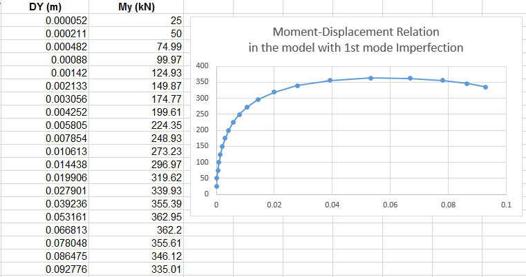
Analysis > Buckling Analysis Control
Q1.Can midas Gen consider second-order incorporating lateral torsional buckling directly?
Analysis > Construction Stage Analysis Control
Q1. There are construction stage load cases, namely, “creep primary”, “creep secondary”, “shrinkage primary” and “shrinkage secondary”. What are the meaning of “primary” and “secondary”, their differences and application?
Analysis > Import Analysis Result
Q1. I try to import the analysis results(*.sar file) into midas Civil.The following error message is displayed:"AN INPUT ERROR OCCURRED AT LINE : 1 PLEASE CHECK INPUT DATA" I think I am making some mistake in the format of sar file. Please advice me.
Results > Combination > Load Combination
Q1. I have a question regarding the load combination import from one model to another in midas Gen. I looked for the procedure in the online manual, but I am not sure of how to generate the .lcb file. What is the procedure of importing or pasting a load combination?
Results > Forces > Beam Forces/Moments
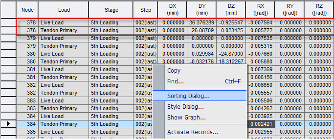
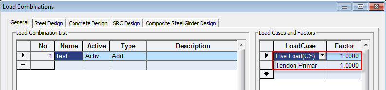
Results > Result Tables > Beam > Forces
Q1. How can I obtain the results for the summation of CS:Live Load and CS:Tendon Primary only?
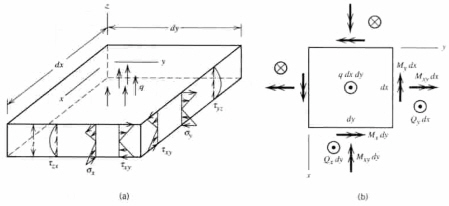
Results > Forces > Plate Forces/Moments
Results > Result Tables > Plate > Force & Stress
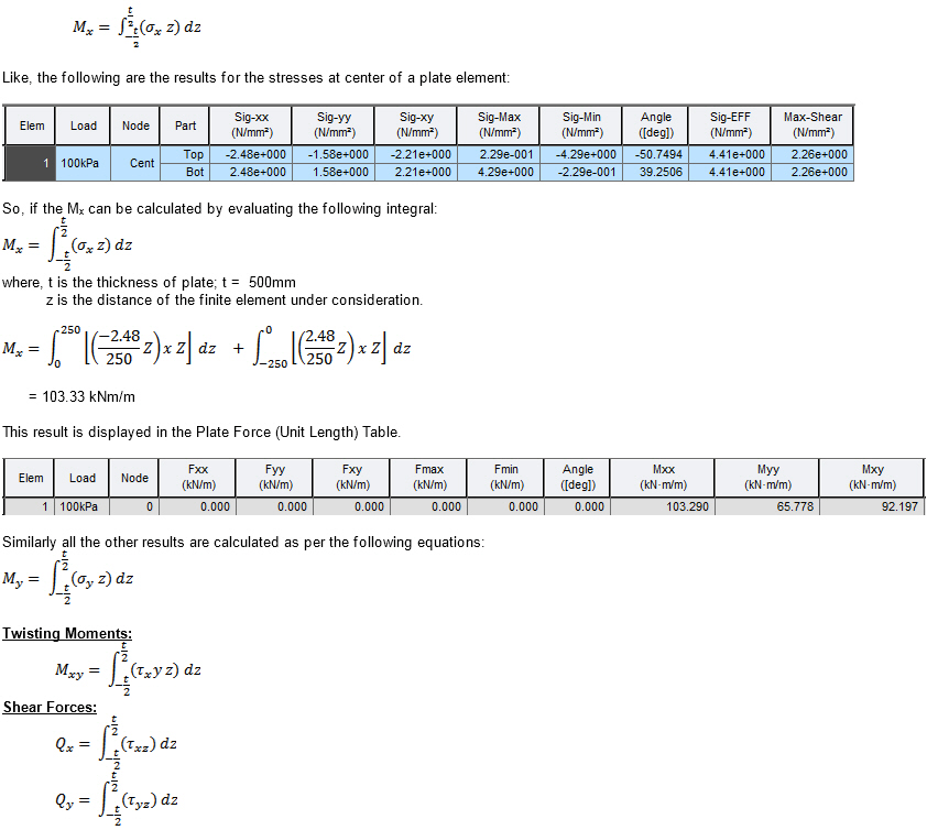
Q1. How can I obtain the results for Plate Force (Unit Length)?
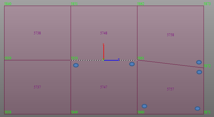
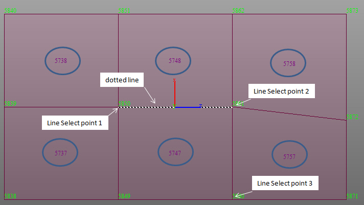
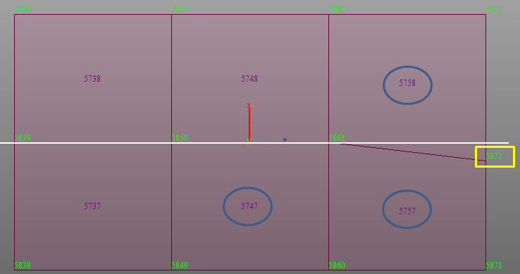
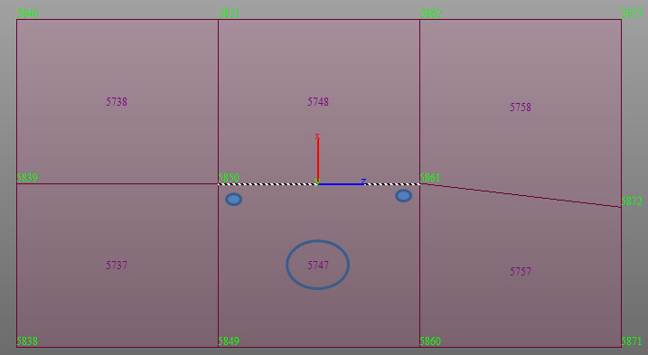
Results > Local Direction Force Sum
Q1. We have a problem with “Local Direction Force Sum”. Please take, for example, the combination 15, the element 70324 and the LDFS named "1elem - X verso il basso". If I run eigenvalue analysis with 100 frequencies some results of LDFS are incorrect, while if I run eigenvalue analysis with 2 frequencies all the results of LDFS are correct. We have attached a file with calculations and the model.
Q2. The results of Local Direction Force Sum of same position are different between the following two cases: Case 1) Six elements are activated in the model view. Case 2) One element is activated in the model view.
Design > Concrete Design Parameter > Serviceability Parameters
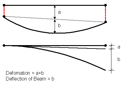
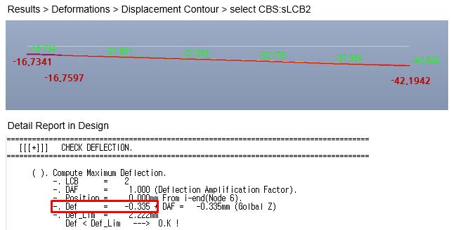
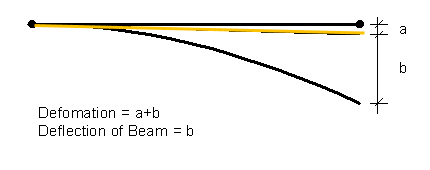
Q1. What is the Deflection Amplification Factor in Serviceability Parameters?
Design > Concrete Code Design > Beam Design
Q1. For Shear Design as per Eurocode2, the load combination being used for design is not the one with maximum shear force. Why?
Design > RC Design > Concrete Code Check > Beam Checking
Design > Steel Design > Steel Code Check
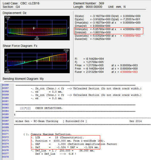
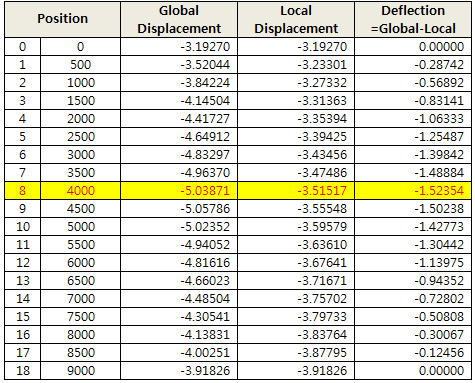
Q1. How midas Gen calculates maximum deflection in a member in Service Limit State Check?
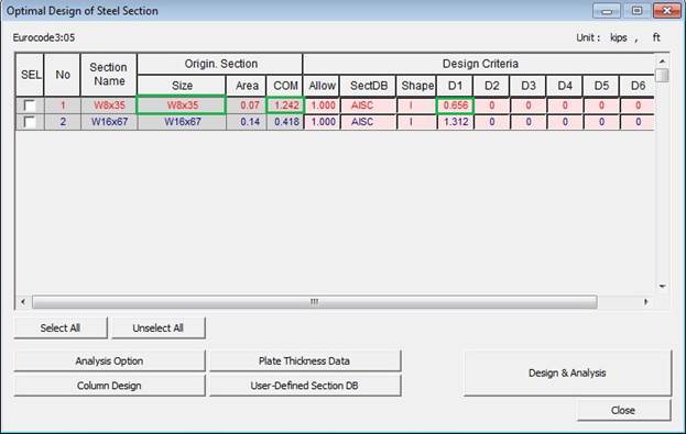
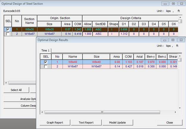
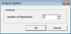
Design > Steel Optimal Design
Q1. In the attached model when I do the optimal design for column the program does not do the design. It does not change the sections. Why?
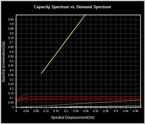
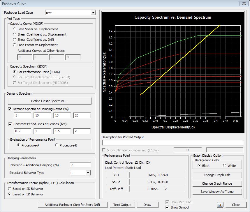
Design >Pushover Analysis > Pushover Curve
Q1. We are doing a pushover analysis of wall element. Our purpose is to analyze the capacity of Steel plate. But the software fails to find the performance point on capacity curve. Why?
Design > Pushover Analysis > Define Hinge Properties
Q1. Is it possible to assign a masonry material type to a wall element when defining the pushover hinges? If not, how should the user overcome this problem?
Tools > General Section Designer
Q1. GSD is hanging up when I perform the design. Why?
|