Static Earth Pressure
Add static earth pressure to spatial structures of general shapes.
When a line element that forms a closed area is selected, the static earth pressure of the area is applied to each node as a nodal load.
From the Main Menu select Load > Static Load > Lateral > Earth Pressure > Static Earth Pressure
 Load Case Name
Assign the load case name. Click
![]() to the right to enter,
additional load cases and modify or delete existing load cases.
to the right to enter,
additional load cases and modify or delete existing load cases.
 Option
Add/Replace: To enter new or additional pressure loads or replace previously entered pressure loads
Delete: To delete previously entered pressure loads
 Direction
X-Y : loads in the horizontal direction of the structure (a direction parallel to the global coordinate system X-Y plane).
Normal : Loads in the direction perpendicular to the load..
 Angle
Angle
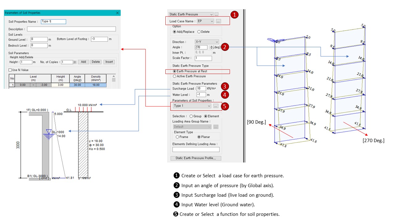
Static earth pressure Enter the input angle in degrees and real numbers for the X-axis of the global coordinate system.
 Inner Pt.
It is activated when selecting Normal in Direction and selects the inner node of the structure.
When Inner Pt. is recognized as the interior of the structure and a load is input to the designated area, the load is applied from the exterior to the interior of the structure.
 Scale Factor
Input static earth pressure increase/decrease factor.
 Static Earth Pressure Type
Select the type of earth pressure to be applied to the static earth pressure calculation.
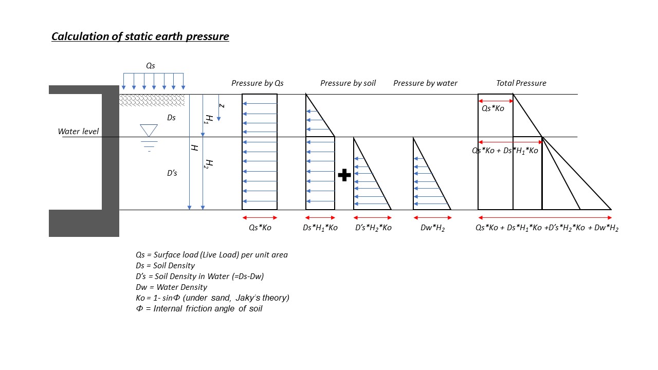
Earth Pressure at Rest: Static earth pressure. It is assumed that the surface of the surface is horizontal and the back of the retaining wall is vertical, ignoring the friction of the retaining wall.
K0(Static earth pressure coefficient) : 1-sinø (Jakyformula)
ø: Internal friction angle of soil, Parameters of Soil Properties value applied.
In general, backfill is a good quality with an internal friction angle of 30 degrees or more. It is supposed to use soil, and it is desirable to use a value of 0.5 or less for K0.
Active Earth Pressure : The main earth pressure. Occurs when the retaining wall moves toward the rear due to the earth pressure when the soil is compressed and destroyed.
Ka(Active earth pressure coefficient) : (1-sinø)/(1+sinø) (Rankine formula)
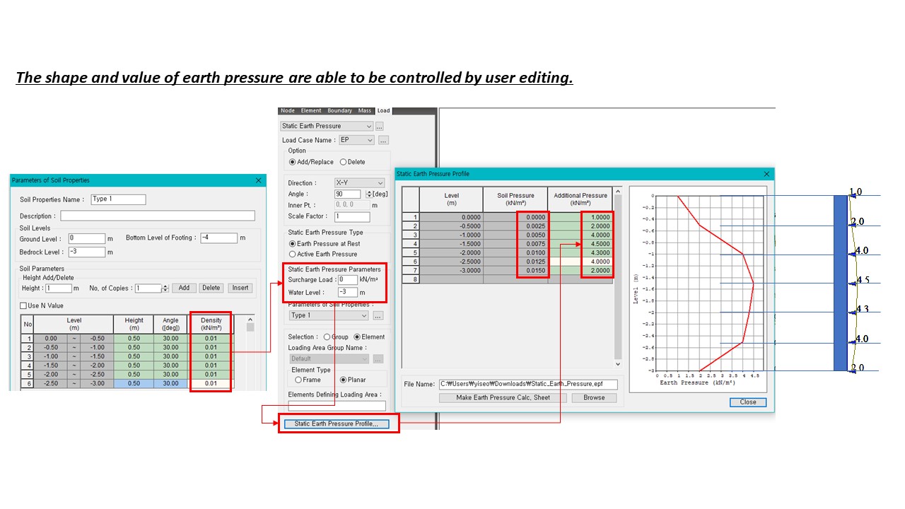
 Static Earth Pressure Parameters
Surcharge Load: It is a kind of overhead load, live load, which is a temporary or temporary load such as equipment movement during construction, storage of materials after construction completion, and vehicle movement.
Water Level: The location of the groundwater level. The unit volume weight of groundwater is considered as 10kN/m3, and the weight of soil at the level of understanding groundwater level is applied as γ-10kN/m3.
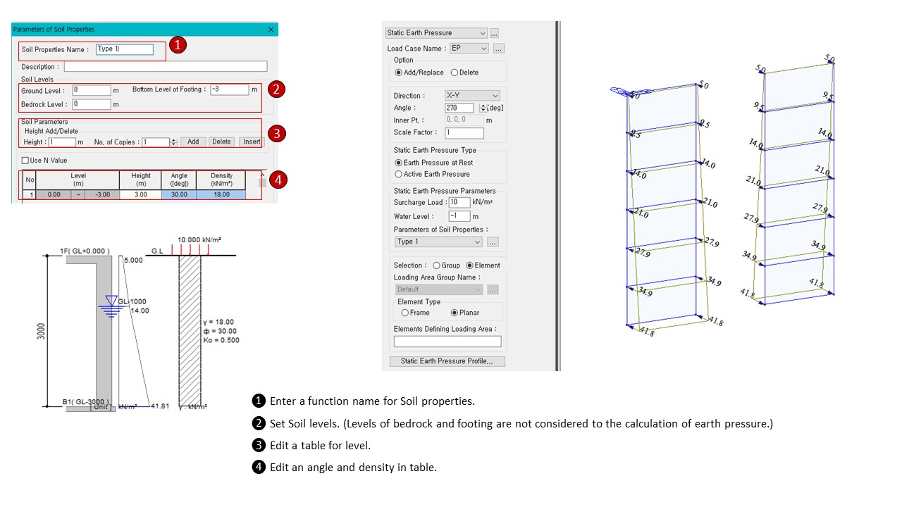
 Parameters of Soil Properties
Soil Properties list corresponding to the code entered in the ground is shown. By pressing the button, you can register ground properties and variables Parameters of Soil Properties
 Selection
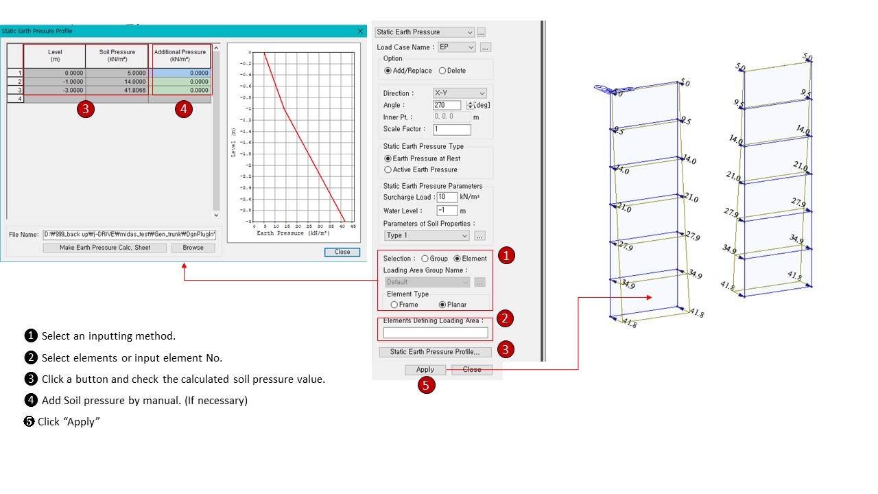
Select the area where Static Earth Pressure will be loaded. The selected area is calculated and input as a concentrated load at the nodes constituting the area.
Group : Enter the load in the Area group set in Load >Loading Area Plane. (If the adjacent member selected in the Loading Area Plane exceeds the 3 degree angle, the closed area cannot be found, so work with caution.
Element : Input the load in the closed area made of the line element selected on the screen.
Note1.
The selected line element must be selected as a closed area, and if there is a closed area inside, the load is input to the nodes within the area only when all the inner line elements are included.
Note2.
When a load is input to a structure composed of only surface elements, such as a structure such as a silo, the load can be input to all nodes only when dummy beams are input between all nodes constituting the mesh and between nodes.
 Loading Area Group Name
Select the Area Group registered in Model> Group> Define Loading Area Group.
![]() Element
Type
Element
Type
Specifies the type of element to generate the load.
Frame : Creates a load at the nodes of the frame element
Planar : Create a load at the node of the plate element
 Element Defining Loading Area
Enter the parameters to be applied to the seismic load calculation.
It is activated when an element is selected in the selection of the loading area, and the line element that forms the closed area is selected (regardless of the order).
 : Display Tables
and Graphs in a spreadsheet form for each loading direction and
component of the auto-calculated seismic load.
 : Display a
spreadsheet Text Output file showing the seismic load calculation
process. Text Editor is automatically executed.
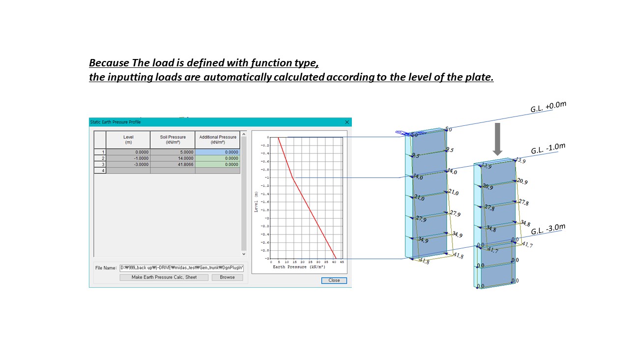
You can check the table and graph in the form of a spread sheet according to the application direction and components of the automatically calculated static earth pressure.
![]() Process
of function
Process
of function
Process of Static Earth Pressure
