Assign Pressure Loads
Apply pressure loads to the faces or edges of plate, plane stress, plane strain, axisymmetric or solid elements. Modify or delete previously entered loads.
The pressure loads are entered as either a uniform pressure or a linearly distributed pressure. The pressure is then converted into equivalent nodal forces in the program.
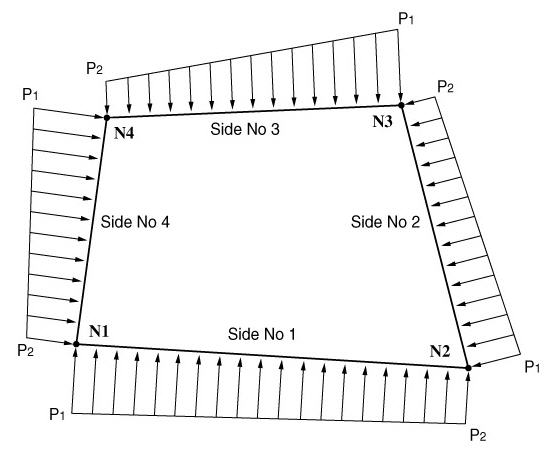
The pressure loads for plate or plain stress elements are entered with respect to the GCS or the element local coordinate system. The direction of the loading applied to the faces coincides with an axis of the given coordinate system. In the case of pressure loads applied to the edges, the loading directions are perpendicular to the edges in the plane of elements. Pressure loads acting towards the elements retain the positive sign (+). Pressure loads acting on the edges are expressed as loads per unit length.
The pressure loads acting on the edges of plane strain and axisymmetric elements are entered perpendicular to the edges. The positive direction (+) refers to loadings applied towards the element edges. In addition, the pressure area is obtained by multiplying the element length by the thickness. Again, the loading is applied per unit length.
The direction of pressure loads applied to solid elements is perpendicular to the faces. The positive direction (+) refers to loadings applied towards the element faces. The loading direction away from the faces retains the negative sign (-).
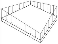
(a) Pressure loads applied normally to the edges of plate, plane stress, plane strain and axisymmetric elements
(b) Pressure loads acting on a face of a plate and plane stress elements
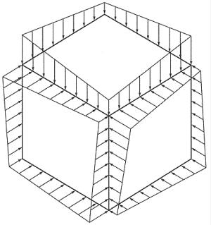
(c) Pressure loads applied normally to the faces of a solid element
<Figure 1> Pressure loads applied on each element
From the Main Menu select Load > Static Load > Pressure Load > Assign Pressure Loads.
|
 Pressure on Plate (Plane Strain, Axisymmetric, Solid Faces)
Specify the locations and directions of the pressure loads by different element types.
Selection
Specify the method of assign the locations of pressure loads
Node: specify nodes (when loads are applied to edges or if solid elements)
Element: specify elements
Pressure Edge
Specify the edges, which pressure loads are to be applied. The specified edge is displayed by a dotted line.
Direction
Normal: Pressure loads applied normally to the face of solid elements
Local x: ECS x-direction of plate or plane stress elements
Local y: ECS y-direction of plate or plane stress elements
Local z: ECS z-direction of plate or plane stress elements
Global X: Pressure loads applied in GCS X-direction
Global Y: Pressure loads applied in GCS Y-direction
Global Z: Pressure loads applied in GCS Z-direction
![]() Vector: Pressure loads are applied in the direction defined by a vector.
Vector: Pressure loads are applied in the direction defined by a vector.
Pressure Face
In the case of solid elements, specify the face to apply pressure loads. The specified face is displyed by dotted lines.
Direction
Local x: ECS x-direction of plate or plane stress elements
Local y: ECS y-direction of plate or plane stress elements
Local z: ECS z-direction of plate or plane stress elements
Global X: Pressure loads applied in GCS X-direction
Global Y: Pressure loads applied in GCS Y-direction
Global Z: Pressure loads applied in GCS Z-direction
![]() Vector: Pressure loads are applied in the direction defined by a vector.
Vector: Pressure loads are applied in the direction defined by a vector.
Projection
When the pressure loads are applied to plate or solid elements in the direction of 'Global X, Y or Z', select whether or not to
project the loads on a plane perpendicular to the loading direction.
Yes: project the pressure loads
No: the pressure loads are applied along the entire face
Loads
Select if the loads are uniformly distributed or linearly varying. Enter the pressure load values.
Uniform: when the pressure loads are uniformly distributed
Linear: when the pressure loads vary linearly
P1, P2, P3, P4: Pressure load values at faces or edges