Deformed Shape


Check the Deformed Shape of the model.


When the pushover analysis or the time history analysis is completed, check the deformed shape of the model for each time step.


Note
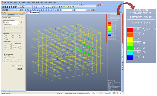
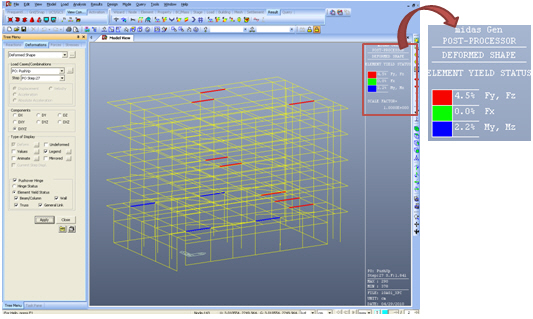
When the pushover analysis is carried out using the inelastic general link elements (Spring Type), the yield status of the general link elements are displayed in the Legend along with the percentage of the hinge status level.


From the Main Menu select Results > Results > Deformations > Deformed Shape.


Load Cases/Combinations


Select a desired load case or load combination.


Click to the right in order to enter a new load combination or to modify the existing one. (Refer to "Combinations")


Step
Specify the step for which the analysis results are to be produced. The Step is defined in geometric nonlinear analysis as Load Step, and additional steps are defined in the construction stages of high-rise buildings or heat of hydration analyses.


Note
The Construction Stage applicable for the output of the construction stage analysis is defined in Select Construction Stage for Display or Stage Toolbar.


Displacement
Display the maximum deformed shape of the model. (Activated after time history analysis). 


Velocity
Display the maximum nodal velocities of the model. (Activated after time history analysis). The magnitudes of the velocities are diagrammatically represented as if the values were displacements.


Acceleration
Display the maximum nodal accelerations of the model. (Activated after time history analysis). The magnitudes of the accelerations are diagrammatically represented as if the values were displacements.


Absolute Acceleration
Display the maximum nodal absolute accelerations of the model. (Activated after time history analysis). The magnitudes of the absolute accelerations are diagrammatically represented as if the values were displacements.


Note1.
Difference between '(Relative) Acceleration' and 'Absolute Acceleration'
Acceleration (Relative) = Acceleration (Absolute) + Observer's Acceleration
As seen from the above expression, Relative and Absolute accelerations differ depending on the presence of Observer's acceleration.


Note2.
Above items become activated only when time history analysis has been performed.


Components


Select the desired deformation component among the following:


DX: Displacement component in GCS X-direction


DY: Displacement component in GCS Y-direction


DZ: Displacement component in GCS Z-direction


DXY =


DYZ =


DXZ =


DXYZ =


Local (if defined) : Where nodes are defined with local coordinate systems, displacements are produced with respect to the local coordinate systems.


Type of Display


Assign the type of display as follows:


Note. Checking the Pushover Analysis Results


Batch Output Generation ( , )


Given the types of analysis results for Graphic outputs, generate consecutively graphic outputs for selected load cases and combinations. A total number of files equal to the products of the numbers of checked items in the three columns of the dialog box below are created. (Details...)