Steel Damper
Add, modify or delete the properties of Steel Damper elements.
From the Main Menu select Boundary > Link > General Link > Seismic Device Properties > Steel Damper
![]() To
enter or add new properties of Steel Damper elements, click the
To
enter or add new properties of Steel Damper elements, click the
![]() button.
button.
![]() To
modify the properties of Steel Damper elements already defined,
select a name from the list of Steel Damper property, click the
To
modify the properties of Steel Damper elements already defined,
select a name from the list of Steel Damper property, click the
![]() button and change appropriate data entries.
button and change appropriate data entries.
![]() To
modify the properties of Steel Damper elements already defined,
select a name from the list of Steel Damper properties, click
the
To
modify the properties of Steel Damper elements already defined,
select a name from the list of Steel Damper properties, click
the ![]() button and change appropriate data entries.
button and change appropriate data entries.
 Name
Name
Enter the name of Seismic Device.
 Hysteresis
Properties
Hyst. Model: Select the Hysteretic model of the steel damper.
Initial stiffness (K0): Enter the initial stiffness of the steel damper.
 Yield
Strength
P1: Enter the first yield strength of the steel damper.
 Stiffness Factor
α1: Stiffness coefficient after first yielding in compression and tension side. (It is defined as α1 * K0.)
α2: Stiffness coefficient after second yielding in compression and tension side. (It is defined as α2 * K0.)
 Hysteresis Parameters
β : Exponent in Unloading stiffness Calculation
θ : Strength Factor (1.0 ≤ θ, Default value is 1.5)
γ : Stiffness Ratio (0 < γ < 1)Select the Hysteretic model for damping coefficient.
 Mounting Parts Stiffness
Kb: Input the additional stiffness depending on the installation of the damper.
 Drawing of Curve by Hysteretic Model
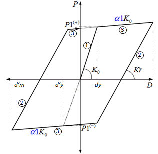
Figure 1. Degrading Bilinear Model |
(1) K1 = K0
(2) K2 = Kr = K0
For Steel, β = 0 For Concrete, β = 0.4
(3) K3 = α1*K0 |
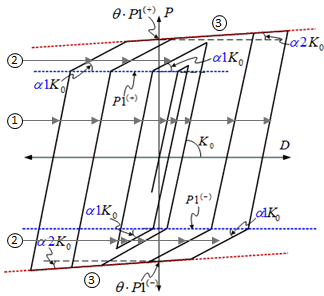
Figure 2. Low Yielding Strength Steel Model(LY2) |
(1) K1 = K0
(3) K3 = α2*K0
|
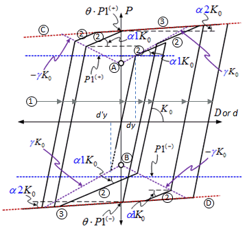
Figure 3. Low Yielding Strength Steel Mode (LY3) |
(1) K1 = K0
(3) K3 = α2*K0
(A) P = P1 – γK0 dy
(B) P = -P1 + γK0 d’y (d’y=dy)
(C) P = θP1 + α2 K0 d
|
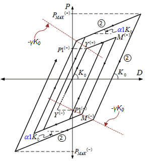
Figure 4. Steel Isotropic-Kinematic Hardening Model |
(1) K1 = K0
|


