Interface Element
To create an interface element.
An Interface element is used when relative displacement is allowed between dissimilar elements or between elements having distinctively different stiffness and where it is not possible to draw a thin layer (because of its thickness relative to entire model).
Applicable Modules:
Ground
|
Slope |
Soft Ground |
Foundation |
Seepage |
Dynamic |
From
the Main
Menu, select Model
> Element > Interface Element ![]()
From the Command Line, type 'InterfaceElement' or 'CEI'
Method
Select the method
of creating interface elements. 
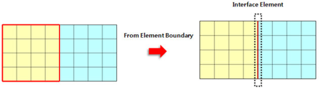
Create from Element Boundary (Mesh Set)
Select interface elements from the outer boundary of elements.
Create from Element Boundary (2D Element)
Create interface elements from the outer boundary of elements.
Note:
Create from Element Boundary: It creates Interface elements from the outer boundary of elements. The diagram below illustrates Interface elements created between the selected element boundary and the adjacent elements.
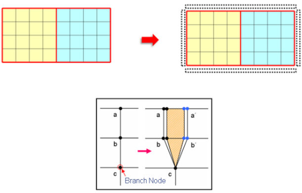
If the entire elements are selected, no Interface elements can be created because of non-presence of adjacent elements. If the Interface elements created are within the interior of mesh, the Interface elements form the shape of a wedge as shown below.
Note:
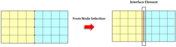
Create by Node Selection: Create interface elements by directly selecting nodes.
Since the wedge shape retains the last node being connected, at least two or more nodes need to be selected to create interface elements.
Note:
Create from Truss/Beam Elements: Create interface elements by selecting Truss/Beam elements.
When Interface elements are created at 1D elements such as Truss/Beam elements, Interface elements are created at both sides of the elements as shown below.
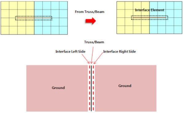
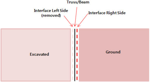
Accordingly, use the option Separately Add Mesh Sets for Interface elements to separately create Interface elements at both sides. Also, when certain ground elements, which are connected to Interface elements, are removed in a Construction Stage, the connected Interface elements are automatically removed at that stage to avoid errors in analysis.
Note:
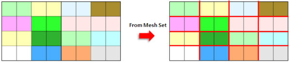
Create from mesh sets (T/X-cross type): When interface elements intersect such as in masonry structures, create interface elements from mesh sets. It creates Interface elements using mesh sets in such case as a masonry structure having intersecting interface elements.
Structural Property
Enter the stiffness
data of interface elements. 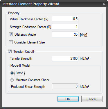
Property Wizard
The stiffness of the interface elements is automatically calculated.
Define Property
The stiffness of the interface elements is directly entered by the user.
Define Wizard
Invoke the dialog box for Interface Element Property Wizard.
Property
Virtual Thickness Factor (tv)
Enter the thickness of the virtual elements.
Strength Reduction Factor (R)
Dilatancy Angle
It represents the ratio between a volumetric strain and a shear strain rate. If un-checked, the same value as the Internal Friction Angle is reflected in analysis.
Consider Element Size
Option to consider the element size in calculating stiffness.
Tension Cut-off
Check in when tension cut-off is considered. It is used to model the soil behavior as it can sustain no or small tensile stress.
Tensile Strength
Input tensile strength at the interface.
Mode-II Model
It represents the failure mode in which separation occurs due to in-plane shear. The shear stress acts parallel to the plane of the crack and perpendicular to the crack front.
Brittle
Model depicting no resistance to shear after cracking. The crack shear modulus, D, is assigned a constant value, which corresponds to a linear ascending relation between shear stress and shear strain across the crack.
Note: In this approach, shear stress can increase indefinitely which may cause numerical instability.
Specific Shear Maintained
The shear stiffness, after cracking, is expressed as a decreasing function of shear function of the crack normal strain. This model accounts for the fact that with increasing crack opening, the interlock of particles diminishes.
Damping Shear Stiffness
Specify the magnitude of the reduced shear stiffness.
Mesh Set
Enter
the name of the interface elements. Click ![]() to Add, Modify or Delete mesh sets.
to Add, Modify or Delete mesh sets.
Create Rigid Link automatically
Check on to automatically create rigid links (X & Z restrained) at the nodes separated by creating interface elements.
Addition of Mesh Set for Interface Elements
When creating interface elements, this option separates the mesh set to create mesh sets for the interface elements.
![]() The dialog box will be initialized.
The dialog box will be initialized.
![]() After creating the elements, the dialog box will close upon clicking.
After creating the elements, the dialog box will close upon clicking.
Click ![]() or press
the ESC key to close the dialog box.
or press
the ESC key to close the dialog box.
![]() After creating the elements, the work
process will switch to the state of Select 2D Element upon clicking.
After creating the elements, the work
process will switch to the state of Select 2D Element upon clicking.