Allowable Tensile Stress
Check the time dependent allowable tensile stress distribution of individual nodes resulting from Heat of Hydration analysis in Contours.
From the Main Menu select Results > Heat of Hydration Analysis > Allowable Tensile Stress.
Select Results > Heat of Hydration Analysis > Allowable Tensile Stress in the Menu tab of the Tree Menu.
|
|
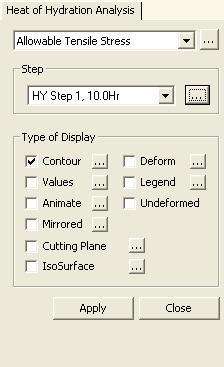
 Type of Display
Define the type of display as follows:
Contour |
Display the allowable tensile stresses of individual nodes resulting from Heat of Hydration analysis in contour. |
|
Ranges: Define the contour ranges.
Note
Number
of Colors: Assign the number of colors to be included
in the contour (select among 6, 12, 18 & 24 colors). Colors: Assign or control the colors of the contour.
Color Table: Assign the type of Colors.
Reverse Contour: Check on to reverse the sequence of color variation in the contour.
Contour Line: Assign the boundary line color of the contour.
Element
Edge: Assign the color of element edges while displaying
the contour. Contour Options: Specify options for contour representation.
Contour Fill
Gradient
Fill: Display color gradient (shading) in the contour.
Draw
Contour Line Only
Mono line: Display the boundaries of the contour in a mono color.
Contour
Annotation Spacing: Specify the spacing of the legend or annotation.
Coarse
Contour (faster) (for large plate or solid model)
Extrude |
Deform |
Display the deformed shape of the model. |
|
Deformation
Scale Factor Deformation
Type
Nodal
Deform: Display the deformed shape only with nodal
displacements. Real Displacement (Auto-Scale off): The true deformation of the structure is graphically represented without magnifying or reducing it. This option is typically used for geometric nonlinear analysis reflecting large displacement.
Relative Displacement: The deformation of the structure is graphically represented relative to the minimum nodal displacement, which is set to "0" |
Values |
Display the allowable tensile
stresses of nodes resulting from Heat of Hydration analysis
in numerical values. |
|
Decimal
Points: Assign decimal points for the displayed
numbers. Min
& Max: Display the maximum and minimum values. Set Orientation: Display orientation of numerical values.
Note |
Legend |
Display various references related to analysis results to the right or left of the working window. |
|
Legend Position: Position of the legend in the display window
Rank Value Type: Specify a type of values in the Legend and the number of decimal points. |
Animate |
Dynamically simulate the time dependent allowable tensile stresses of the solid elements resulting from Heat of Hydration analysis. Click |
|
Animation Mode: Determine the type of animation for analysis results.
Animate
Contour: Option to change the color of the contour
representing the transition according to the magnitudes
of variation
Note AVI Options: Enter the options required to produce the animation window.
Bits
per Pixel: Number of bits per pixel to create the
default window for animation Construction Stage Option: Select the animation options when the construction stage analysis is performed.
Stage
Animation: Animations by construction stages |
Undeformed |
Overlap the undeformed and deformed shapes of the model. |
Mirrored |
"Mirrored" allows the user to expand the analysis results obtained from a half or quarter model into the results for the full model by reflecting planes. |
|
Half
Model Mirroring |
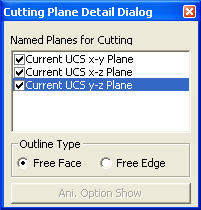
Cutting Plane |
Graphically display the allowable tensile stresses of the solid elements along a cutting plane. |
|
Click the button to access the detail setting dialog box to define the cutting plane to produce and view the solid element stresses resulting from Heat of Hydration analysis. |
|
Named
Planes for Cutting Outline
Type
Free
Face: Draw the outline of all the faces that are
not in contact with other solid elements.
|
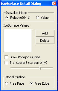
IsoSurface |
IsoSurface searches and displays the planes of equal allowable tensile stresses resulting from Heat of Hydration analysis within the solid elements. |
|
IsoValue
Mode
Relative(0~1) IsoSurface Values Click the
Draw
Polygon Outline Model
Outline
Free
Face: Draw the outline of all the faces that are
not in contact with other solid elements. Note |