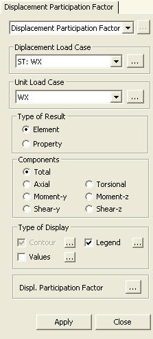
Displacement Participation Factor
Based on a lateral load case, displacement participation by each element for each force component (Axial, Torsional, Moment-y, Moment-z, Shear-y & Shear-z) can be checked in Contour and Value. In order to check the displacement participation factor, a unit load needs to be input in the direction of the lateral load at the location of the maximum displacement.
From the Main Menu select Results > Displacement Participation Factor.
Select Results > Displacement Participation Factor in the Menu tab of the Tree Menu.
|
|
Let us take an example of a simply supported beam, which exhibits a deflection of Δ under the external load L (Fig. 1a). We then apply a unit load at the location of Δ (Fig. 1b) in the same direction of Δ
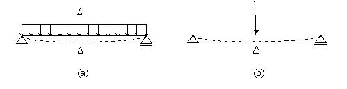
Fig. 1 Unit load method
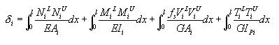
The external virtual work (![]() ) in Fig. 1b is expressed as
) in Fig. 1b is expressed as
![]()
The deflection Δ due to the external
load L in Fig. 1a can be expanded into axial deformation ![]() , flexural deformation
, flexural deformation ![]() , shear deformation
, shear deformation ![]() and
torsional deformation
and
torsional deformation ![]() . And the internal force in the simple beam due to the unit load
is consisted of
. And the internal force in the simple beam due to the unit load
is consisted of ![]() . The internal virtual work
done by the unit load to cause the deformation Δ becomes
. The internal virtual work
done by the unit load to cause the deformation Δ becomes
![]()
If the above beam behaves linearly,
and we define the internal forces caused by the external load
L as ![]() ,
the deformation of the beam element becomes
,
the deformation of the beam element becomes
![]()
We then apply the principle
of virtual work, ( ![]() ), to derive the equation
of the unit-load method.
), to derive the equation
of the unit-load method.
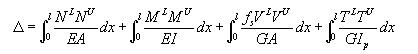
where, ![]() : shape factor for shear
: shape factor for shear
Expanding the concept of the unit
load method to a building subject to a wind load as shown in Fig.
2b, we apply a unit load at the top of the building as Fig. 2a
to find the maximum lateral displacement. If we consider the maximum
displacement due to the wind as a virtual displacement ![]() is the sum of displacements contributed by the individual
elements.
is the sum of displacements contributed by the individual
elements.
![]()
where, m : Number of elements
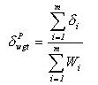
![]() is
said to be the displacement participation of each element, which
is expressed as
is
said to be the displacement participation of each element, which
is expressed as
Displacement participation in a lateral resisting system can be quantified and as such it can be optimized.
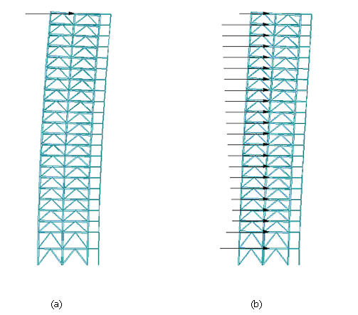
Fig. 2 Unit load application for lateral displacement calculation
 Components
Select a component for displacement participation by elements and section properties.
Total: Sum of displacement participation for all the components
Axial: Displacement participation for axial component in the x-axis direction of the Element Coordinate System
Torsional: Displacement participation for torsional moment component about the x-axis of the Element Coordinate System
Moment-y: Displacement participation for bending moment component about the y-axis of the Element Coordinate System
Moment-z: Displacement participation for bending moment component about the z-axis of the Element Coordinate System
Shear-y: Displacement participation for shear force component in the y-axis of the Element Coordinate System
Shear-z: Displacement participation for shear force component in the z-axis of the Element Coordinate System
![]() Type of Display
Type of Display
Define the type of display as follows:
Contour |
Display the displacement participation of the model in contour. |
|
Ranges: Define the contour ranges.
Note If the Contour Range values exceed the output values, they are entered at Rank 0 and Rank 11.
Number
of Colors: Assign the number of colors to be included
in the contour (select among 6, 12, 18, 24 colors) Colors: Assign or control the colors of the displacement contour.
Color Table: Assign the type of Colors.
Reverse Contour: Check on to reverse the sequence of color variation in the contour.
Contour Line: Assign the boundary line color of the contour
Element
Edge: Assign the color of element edges while displaying
the contour Contour Options: Specify options for contour representation
Contour Fill
Gradient
Fill: Display color gradient (shading) in the contour.
Draw
Contour Line Only
Mono line: Display the boundaries of the contour in a mono color.
Contour
Annotation
Spacing: Display the spacing for the legnd or annotation.
Coarse
Contour (faster)
(for large plate or solid model)
Extrude |
Values |
Display the nodal displacements in numerical values. The font and color of the
numbers can be controlled in |
|
Decimal
Points: Assign decimal points for the displayed
numbers Min
& Max: Display the maximum and minimum values Set Orientation: Display orientation of numerical values
Note |
Legend |
Display various references related to analysis results to the right or left of the working window.
Element numbers pertaining to the maximum and minimum forces are displayed. |
|
Legend Position: Position of the legend in the display window
Rank Value Type: Values for Legend (Exponential or fixed values) |
![]() Type of Display
Type of Display
Click the Displ. Participation Factor button to prompt a dialog box, which shows the prediction of lateral displacement and the change of weights based on changing sections.
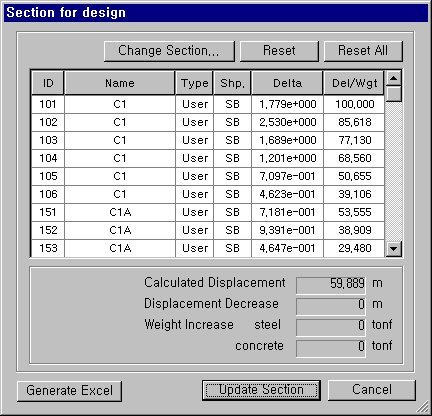
Section for Design dialog box
![]() : Used to change sections selected in the list
: Used to change sections selected in the list
![]() : Used to revert sections selected in the list to the sections
of the original model
: Used to revert sections selected in the list to the sections
of the original model
![]() :
Used to revert all the changed sections to the sections of the
original model
:
Used to revert all the changed sections to the sections of the
original model
Calculated Displacement: Lateral displacement
Displacement Decrease: Change (reduction) of displacement
Weight Increase steel: Increase in weight of structural steel
concrete: Increase in weight of concrete
![]() :
Incorporate the changed sections into the model.
:
Incorporate the changed sections into the model.