Modify Beam Rebar Data
Enter the rebar data and the concrete cover thickness for RC beam members for strength verification.
From the Main Menu select Design > Concrete Design Parameter > Modify Beam Rebar Data.
From the Menu tab of the Tree Menu select Design > Concrete Design Parameter > Modify Beam Rebar Data.
|
|
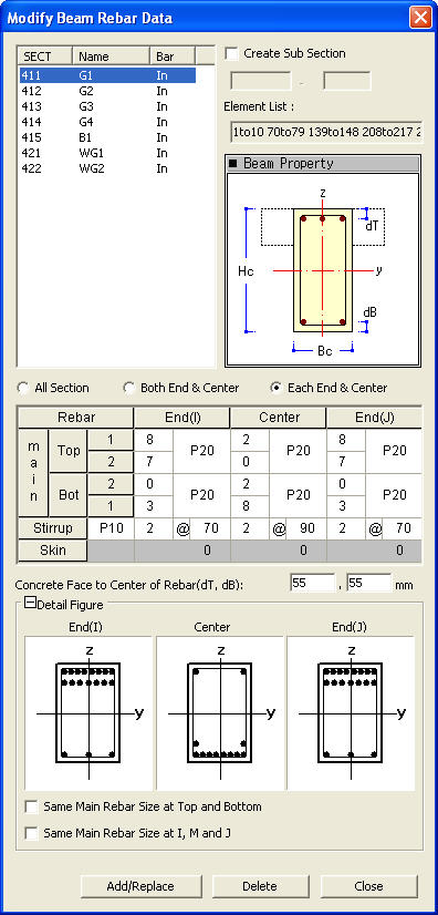
![]() Rebar Data
Rebar Data
Main Rebar
Top: Enter the data of top rebar.
1: Enter the number and size of top Rebar in Layer 1.
2: Enter the number and size of top Rebar in Layer 2.
Bottom: Enter the data of bottom rebar.
1: Enter the number and size of the bottom rebar in Layer 1.
2: Enter the number and size of the bottom rebar in Layer 2.
Stirrup : Enter the rebar size, the number of legs and the spacing of stirrup bars
Note. When IS456:200 design code is selected
Skin : Enter the rebar size and the spacing of side bars
Note.
This row can be activated for torsional strength verification as per Taiwanese design code (TWN-USD92).
![]() Concrete
Face to Center of Rebar
Concrete
Face to Center of Rebar
dT : Distance between the center of the top main rebars in the upper layer and the top surface of the section (cover thickness)
dB : Distance between the center of the bottom main rebars in the lower layer and the bottom surface of the section (cover thickness)
Note
Enter the cover dimensions of the main rebars placed in the outer
layers of the beam members. When the covers are not specified,
(dT = 0, dB = 0), the default value specified by the design code
are applied.
![]() Detail Figure
Detail Figure
Same Main Rebar Size at Top and Bottom: Check on when the top rebar size is identically placed to the bottom rebar size.
Same Main Rebar Size at I, M and J: Check on when the rebar size of i-end, middle and j-end are identically placed.
 Operation
Add/Replace: Add the newly entered values or update the previously entered values.
Delete: Delete the entered values. Data entry is not required when deleting.
Close: Close the dialog box.