Modify SRC Beam Section Data
Enter the rebar data and SRC section data required to perform strength verification of Steel-Reinforced Concrete Composite Beams.
From the Main Menu select Design > SRC Design Parameter > Modify SRC Beam Section Data.
From the Menu tab of the Tree Menu select Design > SRC Design Parameter > Modify SRC Beam Section Data.
First, select the members in the model and enter the following data:
|
|
|
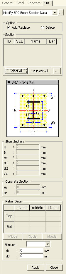
 Concrete Section
Display the concrete section data for the member.
Hc: Height of the concrete section encasing a steel section (outside diameter in the case of a circular section) (refer to Note 2)
Bc: Width of the concrete section encasing a steel section (refer to Note 2)
Rebar Data
Enter the reinforcing data at each position of the beam section for strength verification.
![]() : Enter/modify rebar data at node i of the beam members. The following Definition of Beam Rebar dialog box is displayed:
: Enter/modify rebar data at node i of the beam members. The following Definition of Beam Rebar dialog box is displayed:
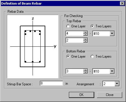
Definition of Beam Rebar Dialog Box
Top Rebar
Enter the top rebar data.
One Layer: Rebar placement in one layer
Two Layers: Rebar placement in two layers
![]() : Number of top rebars in the upper layer
: Number of top rebars in the upper layer
![]() : Number of top rebars in the lower layer
: Number of top rebars in the lower layer
![]() : Rebar size
: Rebar size
Bottom Rebar
Enter the bottom rebar data.
One Layer: Rebar placement in one layer
Two Layers: Rebar placement in two layers
![]() : Number of bottom rebars in the upper layer
: Number of bottom rebars in the upper layer
![]() : Number of bottom rebars in the lower layer
: Number of bottom rebars in the lower layer
![]() : Rebar size
: Rebar size
Stirrup Bar Space: Spacing of stirrup bars
![]() : Enter the values or the selection and close the dialog box.
: Enter the values or the selection and close the dialog box.
![]() : Do not enter the values or the selection and close the dialog box.
: Do not enter the values or the selection and close the dialog box.
![]() : Enter the reinforcing data pertaining to (1/4)L, (1/2)L and (3/4)L positions of the beam members. Data entry is identical to that for i-Node.
: Enter the reinforcing data pertaining to (1/4)L, (1/2)L and (3/4)L positions of the beam members. Data entry is identical to that for i-Node.
![]() : Enter/Modify the reinforcing data at node j of the beam members. Data entry is identical to that for i-Node.
: Enter/Modify the reinforcing data at node j of the beam members. Data entry is identical to that for i-Node.
Stirrup Bar: Spacing of stirrup bars
Arrangement: Number of shear reinforcement legs
dT : Distance between the center of the top main rebars in the upper layer and the top surface of the section (cover thickness) (refer to Note 3)
dB : Distance between the center of the bottom main rebars in the lower layer and the bottom surface of the section (cover thickness) (refer to Note 3)
![]() : Enter the values for the selected section.
: Enter the values for the selected section.
![]() : Close the entry Dialog Bar.
: Close the entry Dialog Bar.
Note 1
Enter the cover dimensions of the main rebars placed in the outer layers of the beam members. When the covers are not specified, (dT = 0, dB = 0), strength verification will not proceed.
Note 2
Rebar data at only one section among the locations of i-Node, Middle and j-Node may be entered. If there are no rebar data, the strength will not be verified.
When rebar data are entered for only one of the i-Node, j-Node and Middle locations: The rebar data will be applied to all the locations for strength verification.
When rebar data are entered for i-Node and j-Node: The i-Node rebar data will be used for the Middle for strength verification.
When rebar data are entered for i-Node and Middle: The i-Node rebar data will be used for j-Node for strength verification.
When rebar data are entered for Middle and j-Node: The j-Node rebar data will be used for i-Node for strength verification.
Note 3
When the rebar data are repeatedly entered for the same SRC member section, the values will be updated to the last values entered.
Note 4
The entered rebar data can be reviewed in the Data Table arranged in the order of section numbers. The user may Modify/Add and Delete items in the data table.
Access the data table as follows:
From the Main Menu select Design > SRC Design Parameter > SRC Design Tables > Modify SRC Section Data.
From the Tables tab of the Tree Menu select Design Tables > SRC Design Table > Modify SRC Section Data.