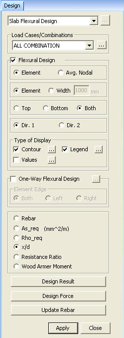
Slab Flexural Design
Check the flexural design results for slab elements in contour. Also check the resulting bending moments and the design results of reinforcement along the specified Cutting Lines.
Note
In order to use this function, Eurocode2:05 or ACI318-11,08,05
must be selected in Design > Concrete Design Parameter >
Design Code.
From the Main Menu select Design > Meshed Slab/Wall Design > Slab Flexural Design
|
Select
a desired load case or load combination. Click
Select to check the flexural design results for a slab.
Element: Display the automatic design results using the internal forces calculated at each node of the element.
Avg. Nodal: Display the automatic design results using the average internal nodal forces of the contiguous elements sharing common nodes.
Element: Depending on the selected option above (Element or Avg.Nodal), produce the automatic design results for moments at each node of the elements that define the slab.
Width: Depending on the selected option above (Element or Avg.Nodal), produce the automatic design results using the average of the moments in the slab elements that contain the selected node.
Top: Design top bars for negative moments.
Bottom: Design bottom bars for positive moments.
Both: Produce the larger of the Top and Bottom bars.
Dir. 1: Display the slab design results for the reinforcing steel entered in Dir. 1.
Dir. 2: Display the slab design results for the reinforcing steel entered in Dir. 2.
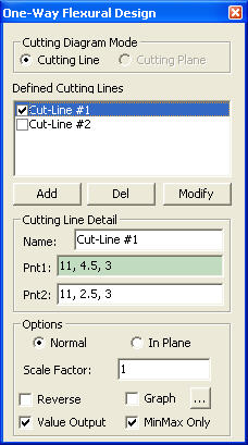
Display the bending moments of the floor slab elements along a cutting line, and produce the design results of reinforcement.[Details...]
Element Edge
Specify the direction to produce the one-way shear check results of the slab elements with reference to the user-defined Cutting Line.
Both: Produce the Max/Min one-way shear check results of the slab elements on both sides of the user-defined Cutting Line.
Left: Produce the one-way shear check results of the slab elements on the left side of the user-defined Cutting Line.
Right: Produce the one-way shear check results of the slab elements on the right side of the user-defined Cutting Line.
Note When the user-defined Cutting Line does not pass through the Mesh Line, Both, Left and Right will produce the same one-way shear check results.
Rebar Display the spacing of rebars in contour, which are placed in a slab using the standard rebar sizes defined in the Design Criteria for Rebars.
As_req(mm^2/m) Display the area of the required reinforcement.
Rho_req The ratio of the area of the required reinforcement to the gross area
x/d The ratio of the neutral axis depth to the effective depth
Resistance Ratio The ratio of the design moment to the moment resistance when the designed rebar spacing is applied.
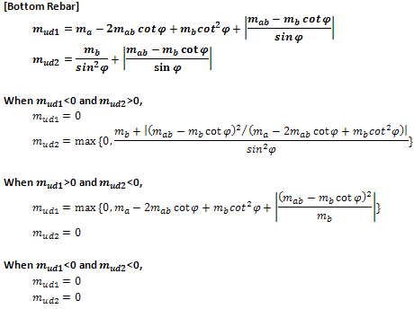
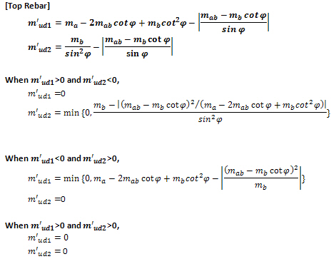
Wood Armer Moment Display the Wood Armer Moments in contour.
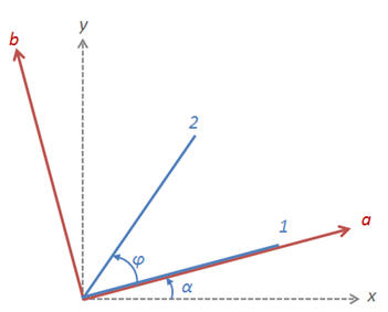
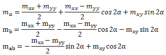
Note. Wood-Armer formula for skew reinforcement
|
 Type
of Display
Type
of Display