Slab Flexural Checking
Perform shear strength verification for the slab.
Note
In order to use this function, Eurocode2:05 or ACI318-11,08,05 must be selected in Design > Concrete Design Parameter > Design Code.
From the Main Menu select Design > Meshed Slab/Wall Design > Slab Flexural Checking
|
|
Select a desired load case or load combination. Click
Select to check the flexural check results for a slab.
Element: Display the strength verification results using the internal forces calculated at each node of the element.
Avg. Nodal: Display the strength verification results using the average internal nodal forces of the contiguous elements sharing common nodes.
Element: Depending on the selected option above (Element or Avg.Nodal), produce the strength verification results for moments at each node of the elements that define the slab.
Width: Depending on the selected option above (Element or Avg.Nodal), produce the strength verification results using the average of the moments in the slab elements that contain the selected node.
Top: Produce the strength verification results for the entered top bars due to negative moments..
Bottom: Produce the strength verification results for the entered bottom bars due to positive moments.
Both: Produce the maximum of the strength verification results for the Top and Bottom bars.
Dir. 1: Display the slab checking results for the reinforcing steel entered in Dir. 1.
Dir. 2: Display the slab checking results for the reinforcing steel entered in Dir. 2.
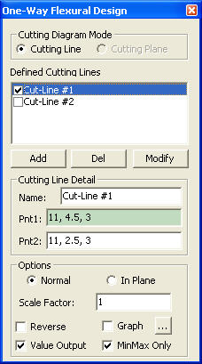
Display the bending moments of the floor slab elements along a cutting line, and produce the design results of reinforcement.[Details...]
Element Edge
Specify the direction to produce the one-way shear check results of the slab elements with reference to the user-defined Cutting Line.
Both: Produce the Max/Min one-way shear check results of the slab elements on both sides of the user-defined Cutting Line.
Left: Produce the one-way shear check results of the slab elements on the left side of the user-defined Cutting Line.
Right: Produce the one-way shear check results of the slab elements on the right side of the user-defined Cutting Line.
Note When the user-defined Cutting Line does not pass through the Mesh Line, Both, Left and Right will produce the same one-way shear check results.
Rebar: Display the spacing of rebars in contour, which are placed in a slab using the standard rebar sizes defined in the Design Criteria for Rebars.
As(mm^2/m): Display the area of the reinforcement defined by the user.
Rho: The ratio of the area of the reinforcement defined by the user to the gross area.
Resistance Ratio: The ratio of the design moment to the moment resistance when the designed rebar spacing is applied.
Wood Armer Moment: Display the Wood Armer Moments in contour.
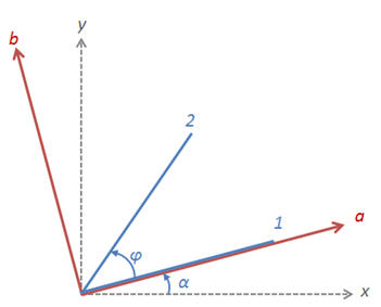
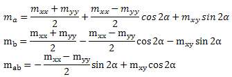
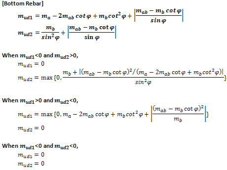
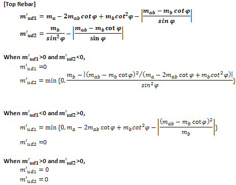
Note. Wood-Armer formula for skew reinforcement
|
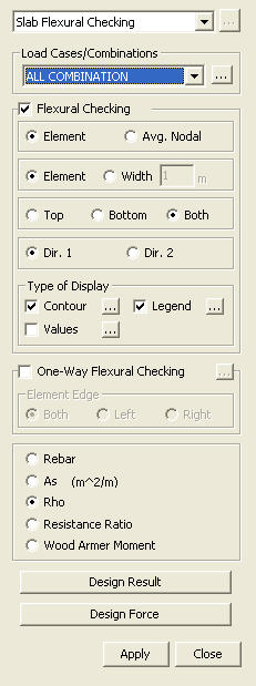
 Type of Display
Define the type of display as follows: