Steel/SRC Optimal Design
Present optimal sections by iterative analysis and optimal design (Section Optimization) processes for the members. Strength verification is carried out based on the structural analysis results, and the Steel Design module or the SRC Design module.
Section Optimization for SRC members is executed through the change of sectional dimensions of the steel members. The sectional dimensions of the concrete, the steel shape and the amount of rebars cannot be changed. The design also satisfies the allowable slenderness ratios.
The function can be accessed only in the Post-processing Mode. While the Steel Design module is running, Steel Optimal Design
cannot be performed. If the SRC Design module is running, SRC Optimal Design cannot be used.
From the Main Menu select Design > Steel Optimal Design.
Shortcut key : [Ctrl]+[F8]
From the Main Menu select Design > SRC Optimal Design.
Shortcut key : [Ctrl]+[F11]
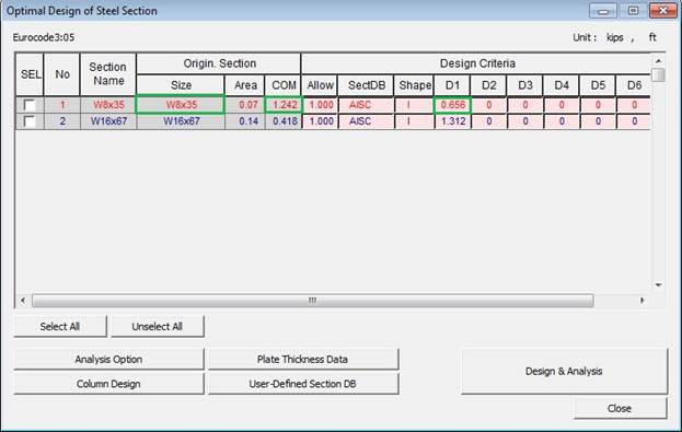
Optimal Design of Steel Section dialog box
SEL
Select sections to be optimized.
Section Name
Member names entered by the user
Orgin. Section
Display the dimensions and strength verification results of the members entered by the user. This part cannot be modified.
Size: Dimensions for the members. "B" is prefixed to the section names for welded built-up sections.
Area: Cross sectional areas of the members
COM: Combined stress ratios (combined strength ratios) due to the strength verification results
Design Criteria
Provide the design criteria required for Section Optimization.
Allow
Enter the desired upper limits for combined stress ratios (combined strength ratios) for the selection of members. The members with the least cross sectional areas within the ratio limits are selected.
If the analysis model is reanalyzed with the changed members incorporated, it may produce results different from the selected combined stress ratios (combined strength ratios) due to the change of the member stiffness ratios.
SectDB
Select the database for design.
There are 5 types of database supported in the program ![]() ,
,
![]() ,
, ![]() ,
,
![]() , and
, and ![]() .
.
![]() creates
welded built-up sections using the member dimensions entered in
D1-D6 and the plate thickness entered in
creates
welded built-up sections using the member dimensions entered in
D1-D6 and the plate thickness entered in ![]() .
.
When ![]() is selected,
the user can use the members (welded sections) entered in
is selected,
the user can use the members (welded sections) entered in ![]() .
.
Shape
Select the member type (shape). The symbols are as follows :
L: L-Steel section
C: C-Steel section
I: I-Steel section
T: T-Steel section
B: Box-Steel section
P: Circular-Steel pipe section
SR: Round Steel bar
SB: Rectangular Steel bar
2L: Double L-Steel section
2C: Double C-Steel section
The member type (shape) can be changed only when the Steel Optimal Design function is used. The type change is not allowed when SRC Optimal Design is used.
D1-D6
Enter the ranges of dimensions to be used for member selections.
If the entry is "0", all dimensions are searched. All subsequent entries after the current item are ignored.
When ![]() is
is ![]() and the entry is
"0" for the member dimensions, the sections are created
using the following data :
and the entry is
"0" for the member dimensions, the sections are created
using the following data :
Section shape |
H1 |
H2 |
H inc |
Remarks |
L-Steel section |
50 |
300 |
10 |
|
C-Steel section |
100 |
800 |
50 |
|
I-Steel section |
100 |
1500 |
100 |
|
T-Steel section |
50 |
500 |
50 |
|
Box-Steel section |
100 |
1500 |
100 |
|
Circular-Steel pipe section |
100 |
1500 |
100 |
|
Round Steel bar |
10 |
200 |
10 |
|
Rectangular Steel bar |
10 |
300 |
10 |
|
Double L-Steel section |
50 |
300 |
10 |
|
Double C-Steel section |
100 |
800 |
50 |
|
Section depth data: if the units in use are 'mm', 'cm', 'm' [Unit : mm]
Section shape |
H1 |
H2 |
H inc |
Remarks |
L-Steel section |
2.0 |
12.0 |
0.5 |
|
C-Steel section |
4.0 |
32.0 |
2.0 |
|
I-Steel section |
4.0 |
60.0 |
4.0 |
|
T-Steel section |
2.0 |
20.0 |
2.0 |
|
Box-Steel section |
4.0 |
60.0 |
4.0 |
|
Circular-Steel pipe section |
4.0 |
60.0 |
4.0 |
|
Round Steel bar |
0.5 |
8.0 |
0.5 |
|
Rectangular Steel bar |
0.5 |
12.0 |
0.5 |
|
Double L-Steel section |
2.0 |
12.0 |
0.5 |
|
Double C-Steel section |
4.0 |
32.0 |
2.0 |
|
Section depth data: if the units in use are 'in', 'ft' [Unit : in]
Section shape |
W1 |
W2 |
W inc |
Remarks |
L-Steel section |
50 |
300 |
10 |
|
C-Steel section |
40 |
400 |
20 |
|
I-Steel section |
100 |
900 |
100 |
|
T-Steel section |
50 |
500 |
50 |
|
Box-Steel section |
100 |
900 |
100 |
|
Circular-Steel pipe section |
- |
- |
- |
|
Round Steel bar |
- |
- |
- |
|
Rectangular Steel bar |
10 |
200 |
10 |
|
Double L-Steel section |
50 |
300 |
10 |
|
Double C-Steel section |
40 |
400 |
20 |
|
Section width data: if the units in use are 'mm', 'cm', 'm' [Unit : mm]
Section shape |
W1 |
W2 |
W inc |
Remarks |
L-Steel section |
2.0 |
12.0 |
0.5 |
|
C-Steel section |
2.0 |
16.0 |
1.0 |
|
I-Steel section |
4.0 |
36.0 |
4.0 |
|
T-Steel section |
2.0 |
20.0 |
2.0 |
|
Box-Steel section |
4.0 |
36.0 |
4.0 |
|
Circular-Steel pipe section |
- |
- |
- |
|
Round Steel bar |
- |
- |
- |
|
Rectangular Steel bar |
0.5 |
8.0 |
0.5 |
|
Double L-Steel section |
2.0 |
12.0 |
0.5 |
|
Double C-Steel section |
2.0 |
16.0 |
1.0 |
|
Section width data: if the units in use are 'in', 'ft' [Unit : in]
When ![]() is a rolled steel section (AISC, BS, DIN, JIS & KS), all the
sections within ± ?% of the entered dimensions are examined for
strength verification. When it is a welded steel section (USER,
BUILT), strength verification is performed only for the sections
that exactly correspond to the entered dimensions.
is a rolled steel section (AISC, BS, DIN, JIS & KS), all the
sections within ± ?% of the entered dimensions are examined for
strength verification. When it is a welded steel section (USER,
BUILT), strength verification is performed only for the sections
that exactly correspond to the entered dimensions.
When all the items are entered with "0", long computation time can result due to an excessive number of members to verify. Enter reasonable ranges to efficiently verify the strength of members.
The data entries for each section shape are as follows :
Section |
Symbol |
D1 |
D2 |
D3 |
D4 |
D5 |
D6 |
L-Steel section |
' L ' |
H |
B |
tw |
tf |
Rop |
|
C-Steel section |
' C ' |
H |
B1 |
tw |
tf1 |
B2 |
tf2 |
I-Steel section |
' I ' |
H |
B1 |
tw |
tf1 |
B2 |
tf2 |
T-Steel section |
' T ' |
H |
B |
tw |
tf |
|
|
Box-Steel section |
' B ' |
H |
B |
tw |
tf1 |
Cw |
tf2 |
Circular-Steel pipe section |
' P ' |
D |
tw |
|
|
|
|
Round Steel bar |
' SR' |
D |
|
|
|
|
|
Rectangular Steel bar |
' SB ' |
H |
B |
|
|
|
|
Double L-Steel section |
' 2L ' |
H |
B |
tw |
tf |
C |
Rop |
Double C-Steel section |
' 2C ' |
H |
B |
tw |
tf |
C |
|
Refer to Help for Section for other details.
![]()
Assign the number of repetitions for strength verification and reanalysis.
![]()
Specify the thicknesses of the plates
to be used when ![]() is
is ![]() .
.
![]()
Enter the data required for optimal design of column members.
![]()
Provide the section dimensions when
![]() is
is ![]() .
.
It executes strength verification
through reanalysis. After repeating analyses with changed members
as many times as assigned in ![]() , it replaces
the original members and analyzes the revised model again.
, it replaces
the original members and analyzes the revised model again.
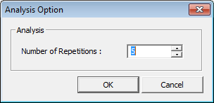
 Analysis Option
Function
Define the number of repetitions for reanalysis with changed members for optimal design.
Entry
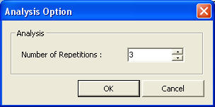
Analysis Option dialog box
Number of Repetitions
Enter the number of repetitions for reanalysis.
The maximum number of repetitions is 10.
Enter "0" when only selecting members without reanalysis.
Upon completing reanalysis with changed members, the results can be reviewed. The model is then revised and analyzed again.
If the analysis is carried out using the members designed to satisfy the design constraints, the results may no longer correspond to the constraints because of the changed member stiffness ratios. If the number of reanalyses is sufficiently increased, results approaching the design constraints can be obtained.
Plate Thickness Data
Function
Enter the thicknesses of flanges and webs to be used in optimal design.
Entry
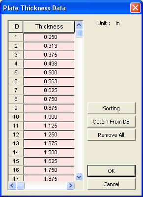
Plate Thickness Data dialog box
Thickness
Enter the plate thicknesses to be
used for members where ![]() is set to
is set to ![]() . A maximum
of 50 types can be used.
. A maximum
of 50 types can be used.
![]()
Show the entered plate thicknesses sorted in an ascending order.
![]()
Obtain the thickness data automatically from the built-in database in the program based on the current unit system.
1) For units 'mm', 'cm' and 'm'
6 mm, 8 mm, 9 mm, 10 mm, 12 mm, 15 mm, 16 mm, 18 mm, 20 mm, 22 mm, 24 mm, 25 mm, 26 mm, 28 mm, 30 mm, 32 mm, 34 mm, 35 mm, 36 mm, 38 mm, 40 mm, 42 mm, 45 mm, 46 mm, 48 mm, 50 mm, 55 mm, 60 mm, 65 mm, 70 mm, 75 mm, 80 mm (total of 32 types)
2) For units 'in' and 'ft'
0.250 in(4/16 in), 0.3125 in(5/16 in), 0.375 in(6/16 in), 0.4375 in(7/16), 0.500 in(8/16 in), 0.5625 in(9/16 in), 0.625 in(10/16 in), 0.750 in(12/16 in), 0.875 in(14/16 in), 1.000 in, 1.125 in, 1.250 in, 1.375 in, 1.500 in, 1.625 in, 1.750 in, 1.875 in, 2.000 in, 2.125 in, 2.250 in, 2.375 in, 2.500 in, 2.625 in, 2.750 in, 2.875 in, 3.000 in, 3.250 in, 3.500 in, 3.750 in, 4.000 in (total of 30 types)
Column Design
Function
Enter the data required for optimal design of column members.
Entry
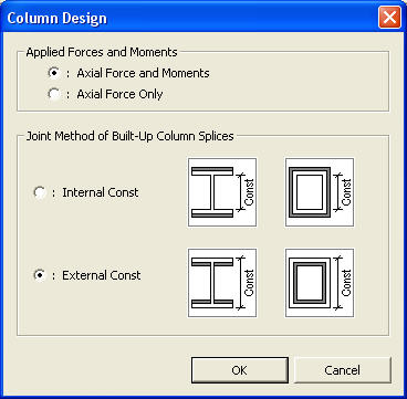
Column Design dialog box
Applied Forces and Moments
Axial Force and Moments
Select the member satisfying the specified conditions which include that the combined stress (strength) due to the axial force (required axial strength) and the moments (required bending strength) is within the allowable stress ratio (allowable strength ratio set in Allow).
Axial Force Only
Select the member satisfying the specified conditions which include that the axial force (required axial strength) is within the allowable stress ratio.
Joint Method of Built-Up Column Splices
For l and box steel sections, when
![]() is set to
is set to ![]() , the
member sizes are determined on the basis of the outer and inner
dimensions of the columns.
, the
member sizes are determined on the basis of the outer and inner
dimensions of the columns.
Internal Const (internal joint mode)
The inner dimensions of a member is fixed with varying depths and/or widths. The plate thicknesses are varied.
External Const (external joint mode)
The outer dimensions of a member are maintained.
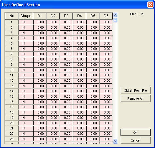
User-Defined Section
Function
Pre-define the sections to be used for Optimal Design. Create the section database by entering complete section data.
Entry
User-Defined Section dialog box
Shape
Define the section shape symbols for the entered data.
When SRC Optimal Design is used, the member shapes cannot be changed from the initially defined shapes. The selection of steel shapes from the section DB will maintain the shapes originally defined for the members.
D1-D6
Enter the principal dimensions constituting the relevant sections. Refer to the D1-D6 entry contents.
![]()
Obtain the section data from a file.
Data File Format
1. Only welded steel sections are permitted. Rolled steel sections cannot be used.
2. The data file starts with "*DB-SECTION".
3. Data components are separated by a space or comma.
4. The first item "ID" may be freely entered as it is a simple identifier.
5. Refer to "Shape" of the main data entry window for the section shapes.
6. D1-D6 are entered in the current unit system. Refer to D1-D6 of the main data entry window.
** Example of input file
*DB-SECTION
**ID, SHP, D1, D2, D3, D4, D5, D6
1, I, 298, 149, 5.5, 9,
2, I, 300, 150, 6.5, 8,
3, I, 300, 300, 10, 15,
4, I, 300, 305, 15, 15,
11, I, 304, 301, 11, 17,
12, I, 350, 350, 12, 19,
13, I, 344, 300, 16, 16,
6, I, 344, 300, 10, 16,
7, I, 900, 250, 10, 25,
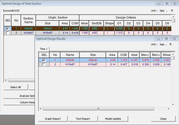
Optimal Design Results
Function
Display and sort the optimal design results in various forms and reflect the change of members in the model.
Entry
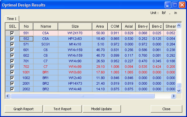
Optimal Design Results dialog box
![]()
Display the results in various forms of charts. The types of output charts are as follows :
Ratio
Display the maximum combined stress ratio (combined strength ratio) for each section.
Weight
Display the resulting variation of the total weights by sections.
Weight Sum
The total weight for each section is individually compiled. The section weight to the extreme right is the total weight.
Weight Ratio
This is the result showing the weights summarized by combined stress ratios (combined strength ratios). The combined stress ratios (combined strength ratios) are displayed at the increment of 0.1(10%).
Average Ratio
Display the average safety ratios by sections. The sum of the ratios for all the members are divided by the number of the members.
Note
The stress ratio '999.0' in the Optimal Design results is produced
when the selected section does not satisfy the allowable slenderness
ratio.
![]()
Produce the results in Text format on the screen and in a file.
![]()
Incorporate the members checked in "SEL" into the original model. Following the verification process the structure is reanalyzed with the new members. The results of reanalysis is displayed in the main entry window.
![]() Revision of Gen 2014 (v1.1)
Revision of Gen 2014 (v1.1)