Global
Settings 
Define globally used parameters within program.
▒ Call
|
▒ Detail Description
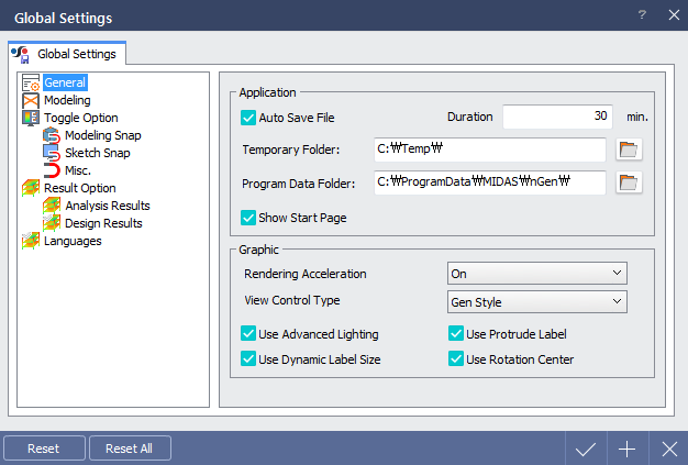
General |
< Global Settings Dialog > |
It is recommended to accelerate rendering if program is to be run in high-quality graphical condition.
midas nGen provides innovative graphical environment compared to previous programs. However, minimum system requirements should be satisfied for smooth performance. There are higher possibility of systematic problem if integrated graphic card is used and Rendering Acceleration will be automatically turned off if integrated graphic card is used within system.
- Operating System : Microsoft Window 7 64bit OS recommended - CPU : Intel Core i3 or higher - RAM : 8GB or more - Graphic Card : NVIDIA Geforce 200 series or higher + Single GPU recommended
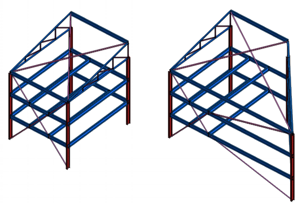
- Mouse Scroll : Move screen - Ctrl + Scroll : Rotate screen - Scroll up : Zoom in - Scroll down : Zoom out
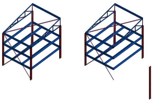
- Mouse Scroll : Rotate screen - Ctrl + Scroll : Move screen - Scroll up : Zoom in - Scroll down : Zoom out |

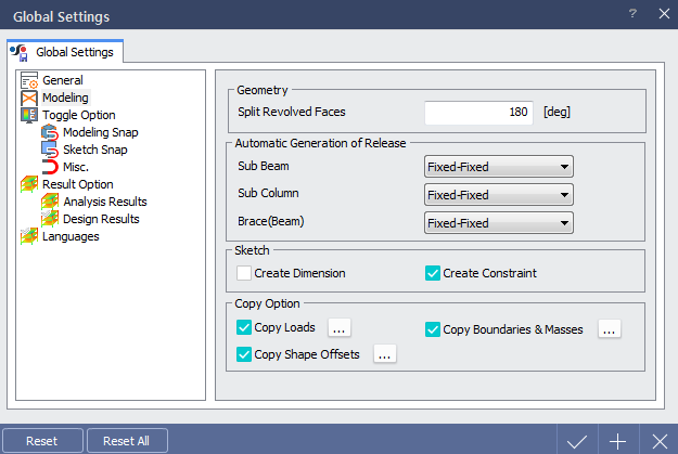
Modeling |
< Global Settings Dialog > |
Define whether to create connection condition automatically as members are created.
Choose whether to copy members with various conditions such as load, boundary condition & mass, shape offset etc.
|
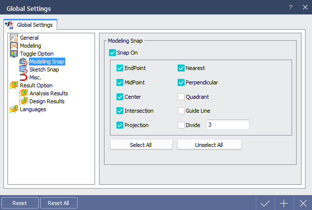
Toggle Option > Modeling Snap |
< Global Settings Dialog > |
Define snap settings used for modeling within 3D and plane mode. Following snap options are provided. |
|
EndPoint |
Snaps to the closest endpoint or corner of a geometric object. |
|
|
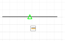
MidPoint |
Snaps to the midpoint of a geometric object.
|
|
|
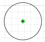
Center |
Snaps to the center of an arc, circle, etc. |
|
|
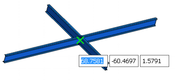
Intersection |
Snaps to the intersection of lines. |
|
|
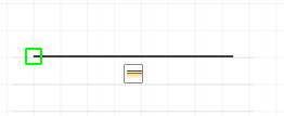
Nearest |
Snaps to the nearest point on a line. |
|
|
Perpendicular |
Snaps to a point perpendicular to the selected line. |
|
|
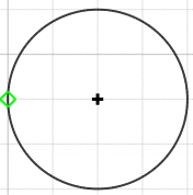
Quadrant |
Snaps to a quadrant point of a circle. |
|
|
Guide Line |
Snaps to the intersection of guide lines. |
|
|
|
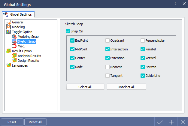
Toggle Option > Sketch Snap |
< Global Settings Dialog > |
Define snap settings used for sketching within sketch mode. Following snap options are provided. |
|
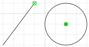
EndPoint |
Snaps to the closest endpoint or corner of a geometric object. |
|
|
MidPoint |
Snaps to the midpoint of a geometric object.
|
|
|
Center |
Snaps to the center of an arc, circle, etc. |
|
|
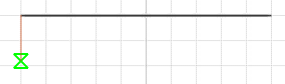
Node |
Snaps to the node. |
|
|
Quadrant |
Snaps to a quadrant point of a circle. |
|
|
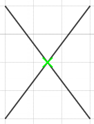
Intersection |
Snaps to the intersection of lines. |
|
|
Nearest |
Snaps to the nearest point on a line. |
|
|
Perpendicular |
Snaps to a point perpendicular to the selected line. |
|
|
Parallel |
Constrains a new line segment to be parallel to an existing line. |
|
|
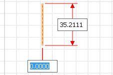
Vertical |
Constrains a line segment to be vertical to the X-axis in sketch mode. |
|
|
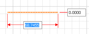
Horizon |
Constrains a line segment to be vertical to the Y-axis in sketch mode. |
|
|
Guide Line |
Snaps to the intersection of guide lines. |
Toggle Option > Misc. |
< Global Settings Dialog > |
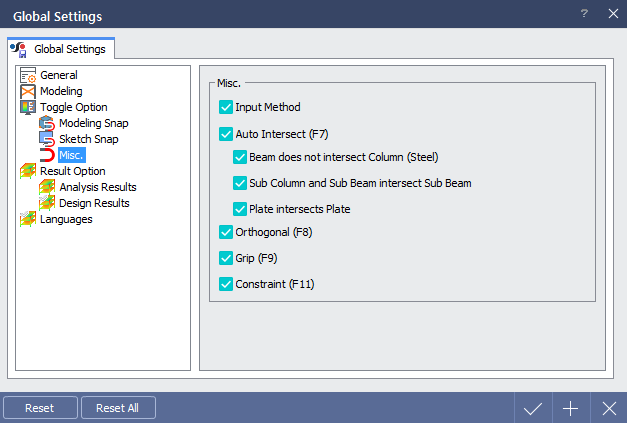
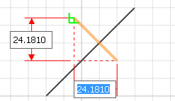
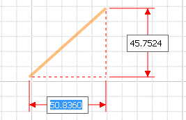
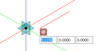
 Input Method (F4) : Change the input method of line
modeling.
Input Method (F4) : Change the input method of line
modeling.
|
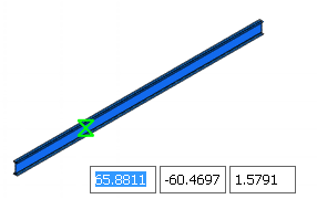
Input Method On |
Express as length of vertical and horizontal components of a line.
|
|
|
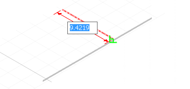
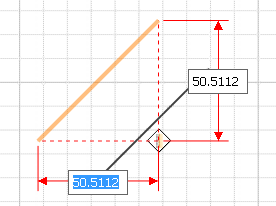
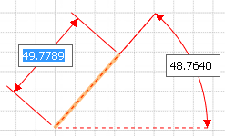
Input Method Off |
Express as length of line and the angle with horizontal axis.
|
Auto Intersect (F7)
: When
members are overlapped to each other, it will be decided whether
to divide those members in accordance with its type.
|
Auto Intersect On |
Divide automatically in accordance to the member type.
|
|
|
Input Method Off |
No automatic division.
|
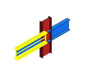
 Beam
do not intersect Column (Steel)
Beam
do not intersect Column (Steel)
 Check
On
:
Beam member does not divide column member.
Only applies to steel members.
Check
On
:
Beam member does not divide column member.
Only applies to steel members.
Check Off
:
Beam member divides column member. Only applies to steel
members.
Sub Column
and Sub Beam intersect Sub Beam
Check On
:
Sub beam member is divided by sub column and sub beam members.
Check Off
: Sub
beam member is not divided by sub column and sub beam members.
Plate
intersect Plate
Check On
:
Plate member is divided by plate member.
Check Off
: Plate
member is not divided by plate member.
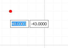
Orthogonal
(F8)
|
Orthogonal On |
Modeling is only possible to the parallel direction of X,Y and Z axis of global coordinate system.
|
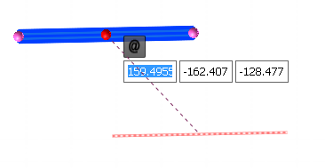
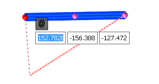
Grip (F9)
|
Grip On |
Small spherical labels will be appeared at begin/end and midpoint of selected object and this can be controlled with mouse to move entire object or the label. |
|
|
Constraint
(F11)
|
Constraint On |
When 1D members or features are moved, coincident conditions between other 1D objects, begin/mid/end point or at any other points will be maintained. |
|
|
Constraint Off |
Coincident condition is not maintained and it moves independently.
|
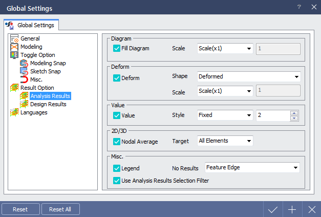
Result Option > Analysis Results |
< Global Settings Dialog > |
Define default settings of analysis results menu.
|
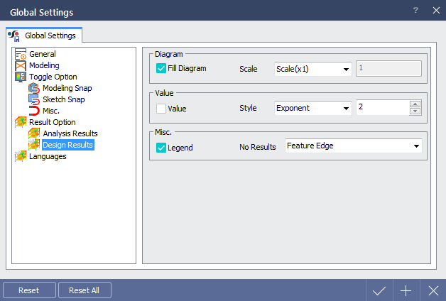
Result Option > Design Results |
< Global Settings Dialog > |
Define default settings of design results menu.
|
|
