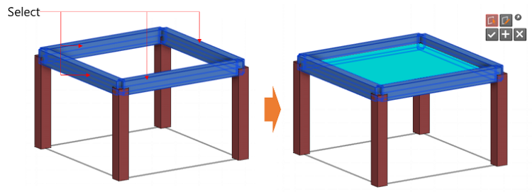
Create slab members(2D)
▒ Call
|
▒ Detail Description
3D Modeling Mode |
< Member Settings & Insert Coordinates >  Member Set
: Select Member Set. Member Set
: Select Member Set.
 Story Set : Select
Story Set. Story Set : Select
Story Set.
 Thickness :
Select Thickness Property. Thickness :
Select Thickness Property.
 Analysis Type
: Select analysis type of wall. Analysis Type
: Select analysis type of wall.
- Membrane : Membrane type is only active with rectangular or Slab Load so it is not included in analysis. This only transfers the loads and used for slab design by codes. - Plate Only : This type of slab is applicable to all shape and load type but this is not included in analysis. It is used to transfer the loads and Plate analysis model is created by Plate Out&In type and design is performed. - Plate Out&In : This type of slab is included in analysis and design is performed based on Plate force. |
|
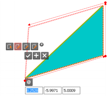
Enter the coordinates of start, mid and end points for generation of slab member using By Draw.
|
Story Mode |
Identical to 3D Modeling Mode |


 (Relative Coordinate) : Define the coordinates of end
point as relative coordinates of start point.