Floor Load 
Enter floor loads within a closed area formed by line members(1D).
▒ Detail Description
|
[Load] Tab > [Gravity] > [Floor Load] > [Floor Load]
Work Tree [Analysis] Tab > [Static Load] > [Floor Load] > [List] > Right-Click > [Modify], [Delete] |

▒ Detail Description
|
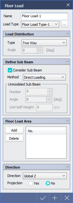
< Floor Load Dialog > |
|
|
Load Distribution |
|
|
Load angle is applicable only for "One Way" Distribution. It is an angle formed by the line connecting the 1st point to the 2nd point defining the loaded area and the load distribution direction. |
|
|
Define Sub Beam |
|
|
|
|
|
Floor Load Area |
|
|
Define the area of floor load.
|
|
|
Direction |
|
|
|
 button.
|
|
