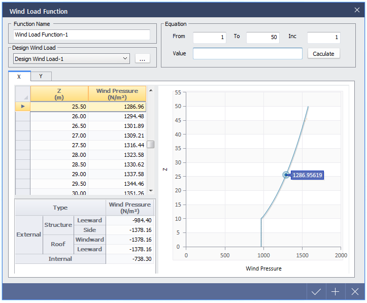
Define wind load function depending on the structure types.
|
Design Wind Load
|
|
Calculate wind load/pressure factors according to wind load code and height of structure to apply wind load, basic wind speed and structure type.
|
|
Mutual Clause
|
|
 Name : Enter the name of wind load. Name : Enter the name of wind load.
Design Code : Select wind load design code. Following wind load standards are supported by midas nGen.
 ASCE 7-10 (IBC 2012) : US, International Building Code 2012 ASCE 7-10 (IBC 2012) : US, International Building Code 2012
ASCE 7-05 (IBC 2009) : US, International Building Code 2009
UBC 1997 : US, UBC 97 standards
EN 1991 : 2005 : Europe, Basis of Design and Actions on Structures
KBC 2009 : KR, Korea Building Code 2009
Range(Z) : Define the height from the ground. Define the height of wind load function to be generated. This is used for calculation of wind pressure in accordance of windward height. If EN 1991 : 2005 code is used, Z value will be used for calculation of wind pressure of windward, leeward and side.

Although the actual height of structure is lower than defined height, corresponding wind pressure of the structure height will be automatically applied. If actual height of structure is lower than defined Z value, wind pressure at maximum Z value will be applied to the structure over height Z.
Average Roof Height (H) : Enter the average roof height. If not defined, maximum Z value is applied and it is used in calculation of windpressure at leeward, side and roof. H value is used to calculate internal pressure and wind pressure at roof when EN 1991 : 2005 code is used.
|
|
KBC 2009
|
|
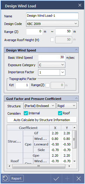
< Design Wind Load Dialog - KBC 2009 Standards >
|
Design Wind Speed
|
|
Enter the variables to calculate design wind speed.
Basic Wind Speed
Exposure Category
Importance Factor
Topographic Factor
|
|
Gust Factor and Pressure Coefficient
|
|
Enter the variables to calculate gust factor and wind pressure.
Structure : Select structure type
(Partial) Enclosed
Opened or Others
Rigid : Rigid structure with natural frequency over 1Hz.
Flexible : Rigid structure with natural frequency below 1Hz.
Internal : Check to consider internal pressure factor.
Roof : Check to wind pressure at roof separately.
Auto Calculate by Structure Information : Variables can be inputted to calculate Wind pressure factor and wind load factor.
|
|
Structure Information – Opened or ETC Type
|
|
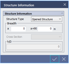
< Structure Information Dialog when Opened or ETC-Opened Sturture is selected >
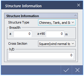
< Structure Information Dialog when Opened or ETC-Chimney, Tank and Similar is selected >
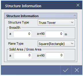
< Structure Information Dialog when Opened or ETC-Truss Tower is selected >
|
Structure Information
|
|
Structure type : If 'Opened or Others' type is selected from Design Wind Load dialog, then select detail type of structure
Opened Structure
Chimney, Tank and Similar
Truss Tower
Breadth : Enter breadth of building to calculate gust factor.
a : Length of structure in a+90-direction (length of surface which is subject to a-direction wind load).
a+90 : Length of structure in a-direction (length of surface which is subject to a+90-direction wind load).
Cross Section : If structure type is chimney, tank and similar type, select section shape as subsection. (Refer to Table 0305.7.4)
Square (Wind normal to face)
Square (Wind along diagonal)
Hexagonal or Octagonal
Round (Moderately Smooth)
Round (Rough)
Round (Very Rough)
Circle
Plane Type : Select plane type if Structure Type is defined as Truss Type.
Square (Steel Pipe) : Select if plane of truss tower is rectangle and formed with steel members.
Square (Rectangle) : Select if plane of truss tower is rectangle and formed with rectangle sections.
Square (Other Type) : Select if plane of truss tower is rectangle and formed with other members.
Triangle (Steel Pipe) : Select if plane of truss tower is triangle and formed with steel members.
Triangle (Rectangle) : Select if plane of truss tower is triangle and formed with rectangle sections.
Triangle (Other Type) : Select if plane of truss tower is triangle and formed with other members.
Solid Area / Gross Area : Fidelity Factor, ratio of actual area facing the wind to the gross area, fidelity ratio
a : Fidelity ratio in a-direction of wind load
a+90 : Fidelity ratio in a+90 direction of wind load
|
|
Structure Information – (Partial) Enclosed Type
|
|
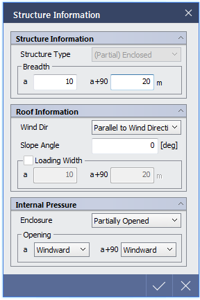
< Structure Information Dialog when (Partial) Enclosed is selected >
|
Structure Information
|
|
Breadth : Enter breadth of building to calculate gust factor.
a : Length of structure in a+90-direction.
a+90 : Length of structure in a-direction.
|
|
Roof Information
|
|
Wind Dir
Parallel to Wind Direction
Normal to Wind Direction
Slope Angle
Loading Width : Check to define Loading Width of wind load manually.
|
|
Internal Pressure
|
|
Enclosure : Type of enclosure
Enclosed
Partially Opened
Excellent Opening
|
|
Structure Information – Flexible Structure
|
|
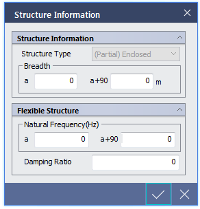
<Structure Information Dialog when Flexible is selected>
|
Flexible Structure
|
|
If 'Flexible' is selected from Design Wind Load dialog, Natural Frequency and Damping Ratio can be defined in Structure Information dialog.
Natural Frequency(Hz)
a : Natural frequency of structure in a-direction.
a+90 : Natural frequency of structure in a+90-direction.
Damping Ratio
|
|
ASCE 7-10 (IBC 2012), ASCE 7-05 (IBC 2009)
|
|
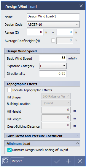
< Design Wind Load Dialog as per ASCE7-10 >
|
Design Wind Speed
|
|
Enter variables to calculate design wind speed.
Basic Wind Speed
Exposure Category
Directionality : Apply 0.85 as default value.
|
|
Topographic Effects
|
|
Enter the variables to calculate toropraphic coefficient.
Hill Shape : Refer to Figure 6-4, ASCE 7-10.
2-D Rigid or Valley
2-D Escarpment
3-D Axisym. Hill
Building Location
Upwind : Select if building is located at upwind direction.
Downwind : Select if building is located at downwind direction.
Hill Height
Hill Length
Crest-Building Distance : Distance between crest and building.
|
|
Minimum Load
|
|
Select to apply minimum wind load.
|
|
UBC 1997
|
|
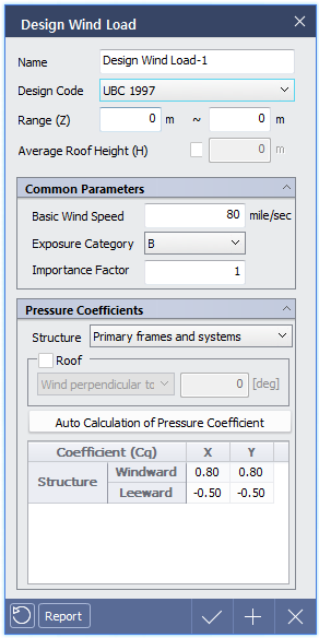
< Design Wind Load Dialog as per UBC 1997 >
|
Common Parameters
|
|
Basic Wind Speed
Exposure Category
Importance Factor
|
|
Pressure Coefficients
|
|
Structure : Select structure type and click 'Auto Calculation of Pressure Coefficient' to obtain wind load/pressure factors automatically.
Primary frames and systems
Primary Partially Enclosed frames
Chimneys, tanks and solid towers (Square or Rectangular)
Chimneys, tanks and solid towers (Hexagonal or octagonal)
Chimneys, tanks and solid towers (Round or elliptical)
Open-frame towers (Square-Diagonal)
Open-frame towers (Square-Normal)
Open-frame towers (Triangle)
|
|
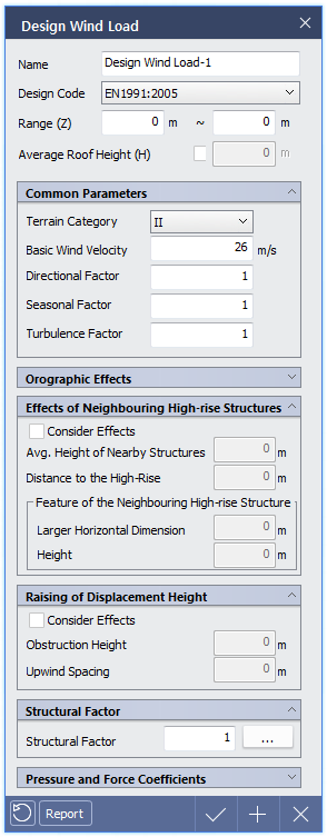
EN 1991 : 2005
|
|
< Design Wind Load Dialog as per UBC 1997 >
< Design Wind Load Dialog as per EN1991:2005 >
|
Common Parameters
|
|
Terrain Category
Basic Wind Speed
Directional Factor
Seasonal Factor
Turbulence Factor
Default values are set as recommended values. Please refer to design standards to apply precise factors.
|
|
Orographic Effects
|
|
Orographic Factors
Orography Category
Cliff or Escarpment
Hills or Ridges
Building Location
Upwind : Select if building is located at upwind direction.
Downwind : Select if building is located at downwind direction.
Height of Topographic Feature
Length of Upwind Slope : Length of slop (in upwind direction).
Length of Downwind Slope : Length of slop (in downwind direction).
Crest Building Distance : Distance between crest and building.
|
|
Effects of Neighboring High-rise Structures
|
|
Enter the variables to calculate change in wind speed due to neighboring high-rise structures. (Please refer to Annex A.4)
Avg. Height of Nearby Structures
Distance to the High-Rise:
Feature of the Neighboring High-rise Structure
Larger Horizontal Dimension
Height
|
|
Raising of Displacement Height
|
|
Enter the variables to calculate change in wind speed due to densely packed structures and obstacles in neighborhood
(Please refer to Annex A.5)
Obstruction Height
Upwind Spacing
Raising of Displacement Height option can be selected if Terrain category is defined as Ⅳ.
|
|
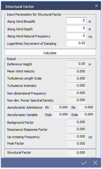
Structure Factor
|
|
Structural Factor(CsCd)
Input Parameters for Structural Factor
Along Wind Breadth
Along Wind Depth
Along Wind Natural Frequency
Logarithmic Decrement of Damping : Enter 'Logarithmic Decrement of Damping' the click Calculate to obtain structural factor. (refer to Annex B)
|
|
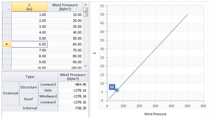
Pressure and Force Coefficient
|
|
Check the results which took into account wind pressure and force coefficients.
Please refer to corresponding design standards for detail information of wind load calculation.
Click 'Report' to obtain wind load report.
|

 .
.