Cad Snap
: Activate/deactivate snap functions for Cad drawing.
Cad Snap
: Activate/deactivate snap functions for Cad drawing.
 Modeling
Snap : Activate/deactivate snap functions for modeling. Modeling
Snap : Activate/deactivate snap functions for modeling.
Snap list and setting
Right-click
to define modeling snap.
|
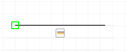
EndPoint |
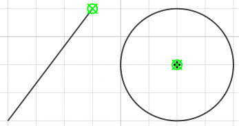
Snaps
to the closest endpoint or corner of a geometric
object. |
|
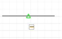
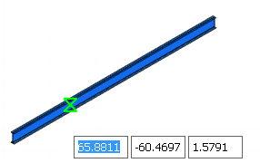
MidPoint |
Snaps
to the midpoint of a geometric object. |
|
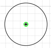
Center |
Snaps
to the center of a circle. |
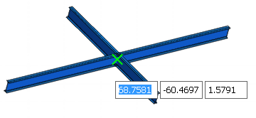 |
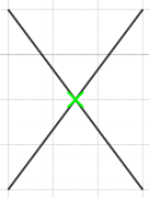
Intersection |
Snaps
to the intersection of geometric objects. |
|
Nearest |
Snaps to
the nearest point on a line. |
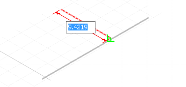 |
Perpendicular |
Snaps to
a point perpendicular to the selected line. |
|
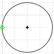
Quadrant |
Snaps
to a quadrant point of a circle. |
|
Guide
Line |
Snaps
to the intersection of guide lines |

Perpendicular snap
and Guide Line
snap
are only available for Plane
Mode.
 Select All Select All
Unsellect
All
Snap on
: Snap functions can be used when selected.
Setting...
: [Structure]
Tab > [Global Settings] > [Global Settings] > Modeling
Snap
 Sketch
Snap : Activate / deactivate snap functions for
sketch. Sketch
Snap : Activate / deactivate snap functions for
sketch.
Snap list and setting
Right-click
to design sketch snap.
|
EndPoint |
Snaps
to the closest endpoint or corner of a geometric
object.
|
|
MidPoint |
Snaps
to the midpoint of a geometric object.
|
|
Center |
Snaps
to the center of an arc, circle, etc. |
|
Node |
Snaps to
the node. |
|
Quadrant |
Snaps
to a quadrant point of a circle.
|
|
Intersection |
Snaps
to the intersection of lines.
|
|
Nearest |
Snaps
to the nearest point on a line.
|
|
Perpendicular |
Snaps
to a point perpendicular to the selected line..
|
|
Parallel |
Constrains
a new line segment to be parallel to an existing
line. |
|
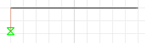
Vertical |
Constrains
a line segment to be vertical to the X-axis in
sketch mode. |
|
Horizon |
Constrains
a line segment to be vertical to the Y-axis in
sketch mode. |
|
Guide
Line |
Snaps
to the intersection of guide lines
|
 Input
Method : Change the input method of line modeling. Input
Method : Change the input method of line modeling.
|
Input Method
On |
Express
as length of vertical and horizontal components
of a line.
|
|
Input
Method Off |
Express as
length of line and the angle with horizontal axis.
|
 Reference
Point : Move reference point of figure. Reference
Point : Move reference point of figure.
|
Reference
Point On |
Move
reference point of figure.
Reference
Point is activated, it is only applied to one
modification.
|
 Auto
Intersect : When members are overlapped to each
other, it will be decided whether to divide those members
in accordance with its type. Auto
Intersect : When members are overlapped to each
other, it will be decided whether to divide those members
in accordance with its type.
|
Auto Intersect
On |
Divide automatically
in accordance to the member type. |
 |
Input
Method Off |
No automatic
division. |
 Orthogonal Orthogonal
 |
Orthogonal
On |
Modeling
is only possible to the parallel direction of
X,Y and Z axis of global coordinate system. |
 Grip
On/Off : Enable to move and modify member by creating
points on the members. Grip
On/Off : Enable to move and modify member by creating
points on the members.
|
Grip On |
Small
spherical labels will be appeared at begin/end
and midpoint of selected object and this can be
controlled with mouse to move entire object or
the label. |
 |
 Constraint
On/Off Constraint
On/Off
|
Constraint
On |
When 1D members
or features are moved, coincident conditions between
other 1D objects, begin/mid/end point or at any
other points will be maintained. |
|
Constraint
Off |
Coincident condition
is not maintained and it moves independently. |
 : Force and Length units
can be changed. : Force and Length units
can be changed.
Status
Bar configuration
Right-click
at Status Bar enables editing of entire menu.the
entire edit of menu. |