Analysis Settings                                                                                                                                                                 

Define the parameters used for analysis.


¢Æ Call

[Analysis] Tab > [Settings] > [Analysis Settings]

Work Tree [Model] Tab > [Project Setting] > [Analysis Settings] > Right-Click > [Modify]


¢Æ Description


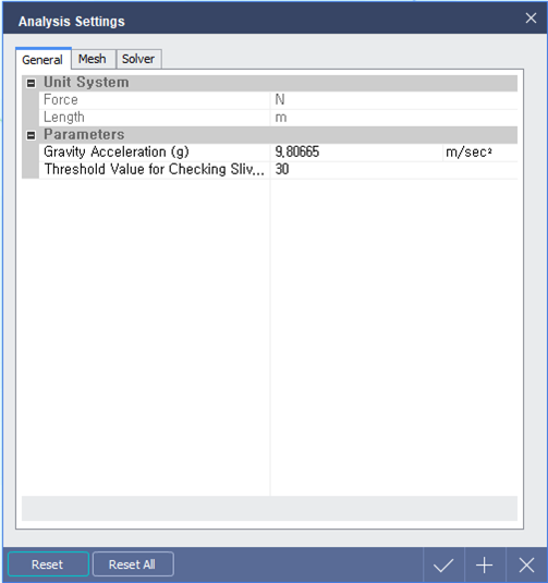
[ Analysis Settings (General) Dialog ]


General

Unit System

Force : Force unit system.

Length : Length unit system.


Modification of unit system is not possible in Analysis Settings dialog. Unit system can be changed in Status Bar located at the bottom right of the program.


Parameters

Gravity Acceleration (g)

        User can modify the Gravity Acceleration (g), if required.


   Threshold value for Checking Sliver Face

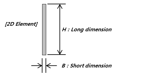
        Enter the threshold value of shape ratio for 2D member. If Threshold value  of 2D element is more than the input value, 2D element will be skipped while running an analysis.


  Threshold value  = Perimeter^2/(4¥ð*Area)

    [Example]

     B: H = 1m : 1m rectangle à 1.27 (= (1m*4)^2 / (4¥ð*1m^2))
              100cm : 1cm rectangle
à  32.47 (= (101cm*2)^2/(4¥ð*100cm^2))

              1000mm :1mm rectangle à  318.95 (= (1001mm*2)^2/(4¥ð*1000mm^2))


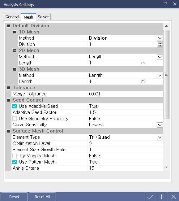
< Analysis Settings (Mesh) Dialog >


Mesh

Default Division

Define the mesh size which is created automatically when analysis is performed.

1D Mesh : Define the mesh size of line member.

Method

Length : Define the mesh size manually.

Division : Define the mesh size by specifying the number of divisions.

By Design Setting : Define the mesh according to the 'Member Check Points' setting at Design Setting.

2D Mesh : Define the mesh size of surface member.

Method

Length : Define the mesh size manually.

Division : Define the mesh size by specifying the number of divisions.

Smart Size : Define the mesh size automatically in accordance to the shape of model

3D Mesh : Define the mesh size of solid member.

Method

Length : Define the mesh size manually.

Division : Define the mesh size by specifying the number of divisions.

Smart Size : Define the mesh size automatically in accordance to the shape of model.


Tolerance

Merge Tolerance : Define Merge Tolerance to combine two or more neighboring points as single point.


Surface Mesh Control

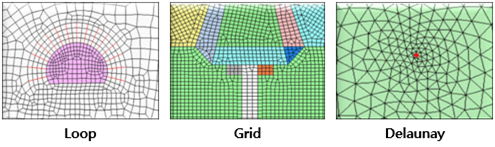
Define 2D mesh generation method.

2D Mesher : Select 2D mesh generating algorithm.

Loop Mesher : Mesh generation method and shape based on Looping Algorithm

Grid Mesher : Complex mesh generation based on Modified Grid algorithm.

Delaunay Mesher : Indirect mesh generation based on Delaunay triangulation algorithm.


Element Type : Generate a mesh with the selected shape.

Triangle :  Generate a mesh with triangle.

Quadrilateral : Generate a mesh with quadrilateral.

Tri+Quad : Generate a mesh with combination of triangle and quadrilateral

Quadrilateral meshes provide a more stable analysis, but for complex geometric shapes where quadrilateral meshes are difficult to generate, it is better to generate a triangular mesh.


Element Size Growth Rate : Define the internal mesh density to create mesh with higher quality.


Tri Mapped Mesh : Select whether to generate Mapped Mesh or not.

The Mapped mesh maps the selected shape with square domains and generates a mesh on the mapped domain.


Use Pattern Mesh : Generate Pattern Mesh which is designed to achieve the best quality mesh when an object surface becomes rectangular when it is spread out on a plane.


Volume Mesh Control

 Define 3D mesh generation method.

3D Mesher : Select 3D mesh generating method.

Default Tetra Mesher : Mesh generation based on basic tetrahedral mesh shape

High Speed Tetra Mesher : Mesh generation based on Hybrid mesh shape

Like the 2D mesh, quadrilateral-based meshes provide more stable analysis than triangle-based meshes. Hybrid elements are formed by combining a pyramid and tetrahedron on the hexahedron base.  


Mid Nodes On Geometry : High-Order member generation

Generate another point between mesh points for a more detailed analysis, but the analysis time becomes longer per additional point.  


  Element Size Growth Rate : Define the internal mesh density to create mesh with higher quality.


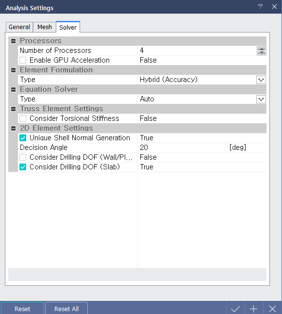
< Analysis Settings (Solve) Dialog >


Solve

Processors

Number of Processors : Specify the number of CPUs used for analysis. For a dual core CPU, input 2 processors and for a quad core CPU, input 4 processors to increase the analysis speed.

Enable GPU Acceleration : Select whether to enable GPU Acceleration or not.


Element Formulation : Define element formulation.

Hybrid (Accuracy)

Reduced (Efficiency)

Standard (Stability)

In terms of analysis speed, the order is ¡°Reduced(Efficiency) > Standard(Stability) > Hybrid¡±. In terms of accuracy, the order is "Hybrid > Reduced > Standard".


Equation Solver : Select the analysis solver to be performed.

If it is defined as 'Auto', one of Multi-Frontal, Dense matrix and AMG(algebraic multi-grid) method is used.


Truss Element Settings : Define analysis variables of truss member.

Consider Torsional Stiffness : Check to consider Torsional Stiffness in axial direction.


2D Element Settings : Define analysis variables of 2D member.

Decision Angle : If the orthogonal vector angle between adjacent two 2D elements exceeds Decision Angle, analysis results will be plotted by assuming that they are laid on the different planes.

If the mesh on curve is not smooth because the size of mesh is considerably larger than the curvature, the decision angle should be increased to obtain smooth contour by considering the curvature of geometry.


Consider Drilling DOF : This option calculates in-plane stiffness by considering out-of-plane drilling DOF.