Basement Wall
Create Basement Wall member(2D).
It is automatically assigned to the “Basement” member set, and designed by FEA Method. It is classified as an basement wall member in drawings and reports, and the default cover is 80mm.
▒ Call
[Member] Tab > [Basement] > [Basement Wall] Work Tree [Model] Tab > [Member] > [Member Set] > [Basement Wall] > [List] > Right-click > [Delete] |
▒ Detail Description
| 3D Modeling Mode |
[Member Settings & Insert Coordinates]
 Member
Set :
Select Member Set.
Story Set :
Select Story Set.
Thickness :
Select Thickness Property.
Analysis Type
: Select
analysis type of wall. Member
Set :
Select Member Set.
Story Set :
Select Story Set.
Thickness :
Select Thickness Property.
Analysis Type
: Select
analysis type of wall.
- Membrane : Member with no stiffness in minor axis(thickness) direction. Mesh analysis is not performed. - Plate-Not Meshed : Member with stiffness in all direction. Mesh analysis is not performed. - Plate-Meshed : Member with stiffness in all direction. Mesh analysis is performed. |
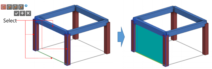
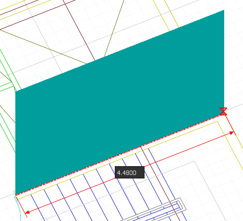
 By Select : Create wall by selecting
closed section formed from Grid Line, 1D member, Edge of 2D member
etc. By Select : Create wall by selecting
closed section formed from Grid Line, 1D member, Edge of 2D member
etc.
|
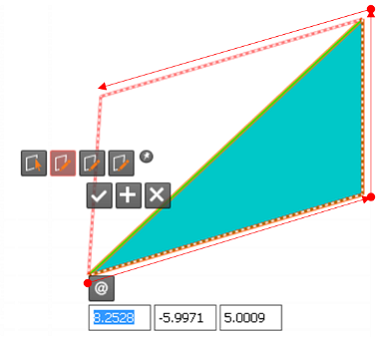
[Note]
 (Relative Coordinate)
: Define the coordinates of end point as relative coordinates
of start point. (Relative Coordinate)
: Define the coordinates of end point as relative coordinates
of start point.
|
| Story Mode |
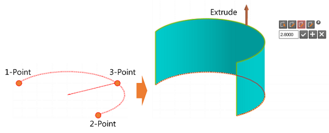
| Wall generation method is same as that
of 3D Modeling Mode but the height of wall member is automatically
taken from story height data.
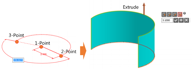
Additional, wall generation using CAD Tracing have been added as follows. |
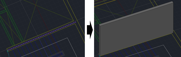
[Reference Line Mode] - Create wall by recognizing two parallel lines among the selected lines. Wall is generated in the center position of two lines and the length of the wall is identical to the shorter line. |
[Wall Mode] - Create wall by recognizing two parallel lines among the selected lines. Wall is generated in the center position of two lines and the length of the wall is identical to the shorter line. - all thickness is automatically recognized and generated in thickness properties. - Wall thickness is automatically recognized and generated in thickness properties. |


|
