|
▒ Overview
 The Seepage Cut Off (SCO) element can be used to simulate the behavior of structural waterproof members. Main role of the element is to control seepage DOF on the line or face The Seepage Cut Off (SCO) element can be used to simulate the behavior of structural waterproof members. Main role of the element is to control seepage DOF on the line or face
▒ Methodology
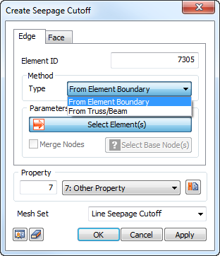
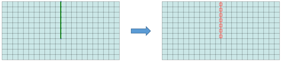
In 2D analysis, select a line element (From Element Boundary/Truss/Beam element) to define the impermeability.
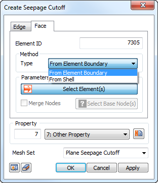
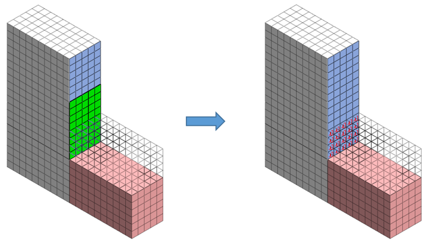
In 3D analysis, the impermeability can be defined by selecting the face element (From Element Boundary/Shell element).
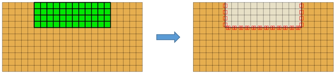
From Element Boundary
Create an SCO element at the boundary position between the selected element and adjacent element, as shown in the figure below.
Selecting all elements cannot create an SCO element because there are not adjacent elements.
From Truss/Beam (for 3D case - Shell element)
Create an SCO element using the truss/beam element.
For 3D, use a plate element.
Creating a seepage cut off element for structural elements such as truss/beam/shell generates “impermeable interface” element on both sides of the element.
▒ Property
Checking the Seepage Flow DOF option allows for control the flow rate/impermeability characteristics.
(※ When checked: consider the effect of seepage, when not checked: consider the impermeability effect)
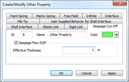
The effective thickness used in Seepage Flow DOF is the effective thickness for the imaginary size used for the calculation of the seepage flow and it defines the width of the structural member
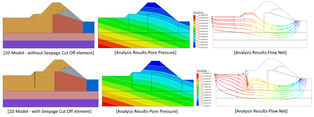
▒ Results Comparison
2D analysis case (via Truss/Beam element type)
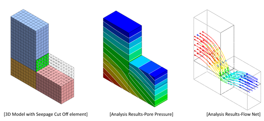
3D analysis case (via Shell element type)
|