Use Plate Wizard to auto-generate a rectangular, circular or semicircular
plate structure composed of Plate Elements.
From the Main
Menu select Model > Structure Wizard > Plate.
Select Geometry
> Structure Wizard > Plate from the Menu tab of the Tree Menu.
Shortcut key:
[Ctrl]+[Shift]+Z
Input
dialog box
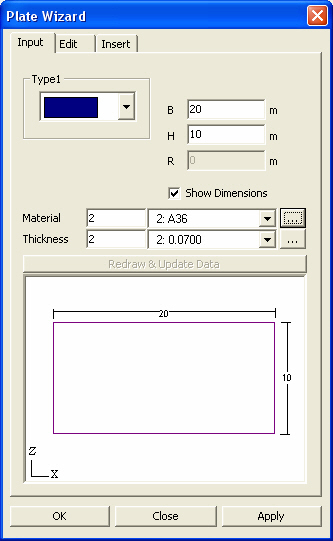
Input tab
Type
Enter the shape (rectangular, circular or semicircular) of the plate structure
to be created.
B
Enter the width of the plate structure.
H
Enter the height of the plate structure.
R
Enter the radius of the plate structure (circular or semicircular).
Show Dimensions
Display the dimensions entered in the Wizard Window.
Material
Enter the material property to be used.
Click to add a new material
property or modify an existing material property.
Thickness
Enter the thickness to be used.
Click to add a new thickness
or modify an existing thickness.
Edit dialog box
Edit tab
Type
Select the shape of an opening (none, rectangle or circle) in the plate
structure to be created.
Size of
Divisions
Enter the division spacing of the plate structure.
Number of
Divisions
Enter the numbers of divisions in the plate structure, in both x &
z directions.
The numbers of divisions apply only when
there is no opening.
Size
Enter the maximum size (side length) of a plate element.
m, n
For a rectangular plate structure, enter the numbers of divisions for the
width (m) and height (n).
Db, Dh
Enter the distances between the center of the plate structure and the center
of the opening.
Enter the distances in the directions of
the width (Db) and height (Dh).
b, h
For a rectangular opening, enter the width and height.
r
For a circular or semicircular opening, enter the radius.
Show Sub-dimensions
Display the dimensions of the opening.
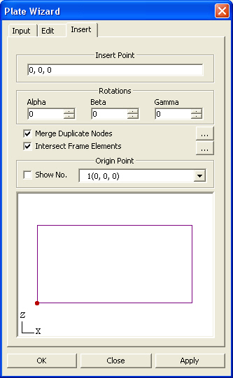
Insert dialog box
Insert tab
Insert
Point
Enter the coordinates of the insert point
where the origin point of the created plate structure will be located
in the existing model with respect to the GCS (UCS).
Alternatively, click the entry field and
click the position of the insert point in the working window to enter
the desired coordinates rather than typing in the entry field.
Rotations
Enter the rotational angles, Alpha, Beta and Gamma, that will define the
orientation of the plate structure in GCS X, Y and Z respectively.
Merge Duplicate
Nodes
Select the option whether to merge overlapping nodes between the existing
model and the nodes pertaining to the newly created plate structure.
: Set a tolerance for
merging nodes.
Intersect
Frame Elements
Select the option whether to divide the existing elements at the nodes
pertaining to the newly created plate, which are in contact with the existing
elements in the existing model.
: Set an intersecting
tolerance to allow for the division of elements.
Origin Point
Set the origin point of the newly created plate structure. This point is
displayed in red in the Wizard Window.
Show No.:
Display the node numbers making up the created plate structure.
 Input tab
 to add a new material
property or modify an existing material property.
to add a new material
property or modify an existing material property.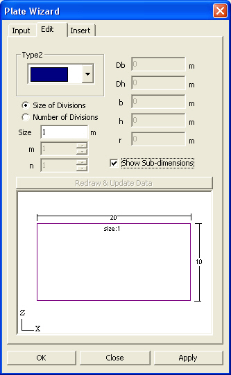
 Insert
Point
Insert
Point