Move or copy elements symmetrically with respect to a particular Mirroring
Plane.
From the Main
Menu select Model > Elements > Mirror.
Select Geometry
> Elements > Mirror in the Menu tab of the Tree Menu.
Click Mirror Elements in the Icon Menu.
Shortcut key:
[Alt]+6
Click to the right of Mirror Elements : Display the Element
Table.
Start Node Number
Assign a starting number of the nodes automatically
created in the element generation process. This number is auto-set to
the largest node number in use +1. To modify this item, click and select an option to specify a desired number.
Start Element Number
Assign a new starting element number for
new elements being created by copy. This number is auto-set to the largest
element number in use +1. To modify this item, click and
select an option to specify a desired number.
Mode
Copy:
To copy elements
Move:
To move elements
Reflection: Assign the mirroring plane.
y-z plane:
Mirroring plane is parallel to the y-z plane.
x: x coordinate of the mirroring plane
x-y plane:
Mirroring plane is parallel to the x-y plane.
z: z coordinate of the mirroring plane
z-x plane:
Mirroring plane is parallel to the z-x plane.
y: y coordinate of the mirroring plane
Plane defined
by 3 pts.: Mirroring plane is an arbitrary plane.
x1, y1, z1: x, y, z coordinates of the 1st point defining
the mirroring plane
x2, y2, z2: x, y, z coordinates of the 2nd point defining
the mirroring plane
x3, y3, z3: x, y, z coordinates of the last point
defining the mirroring plane
The coordinates of the three points may be
directly typed in on the keyboard. Alternatively, click the relevant entry
field and the desired point in the working window to enter the x, y, z
coordinates.
Material
Increment: An increment for material property numbers while copying
elements
Section
Increment: An increment for section numbers while copying elements
Thickness
Increment: An increment for thickness numbers while copying elements
Intersect
Applicable only for line elements
If Intersect
Node is selected, and existing nodes are on the created line elements,
the elements are divided at the existing nodes.
If Intersect
Element is selected, and the created line elements intersect with
existing line elements, nodes are automatically created and the elements
are divided at the intersections.
Copy Node
Attributes
Select the option whether to copy the attributes (nodal boundary conditions,
nodal concentrated loads, etc.) to the nodes being copied. Click to assign desired attributes selectively.
Copy Element
Attributes
Select the option whether to copy the attributes (element boundary conditions,
element loads, etc.) to the elements being copied. Click to assign desired attributes selectively.
Mirror Beta
Angle
While copying or moving elements by mirroring, select whether to mirror
the Beta Angle attributes to be symmetrical about the reflecting plane.
Reverse Element Local
While copying or moving elements by mirroring,
select whether to mirror the ECS to be symmetrical about the reflecting
plane.
For Line
Element, Beta Angle remains unchanged and only nodes i, j (Local
Direction) are changed.
For Planar
Element, the node entry sequence is reversed during the generation
of elements.
For Solid
Element, the node entry sequence is reversed during the generation
of elements.
Specify a merging tolerance to merge newly
created nodes and existing nodes.
 Mirror Elements
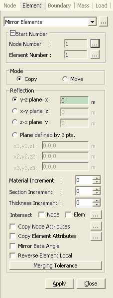
 to the right of
  Start Node Number
 x
x