Enter the end release conditions (Hinge, Sliding, Roller Joint and Partial
Fixity) at both ends of beam elements, or replace or remove previously
entered end release conditions.
Beam End Offsets can be specified in conjunction with (Beam
End Offsets).
From the Main
Menu select Model > Boundaries > Beam End Release.
Select Geometry
> Boundaries > Beam End Release in the Menu tab of the Tree Menu.
Click
to the right of Beam
End Release: Display the Beam End Release Table
Boundary Group Name
Select a Boundary Group in which the specified
boundary condition is included. Select "Default" if Group assignment
is unnecessary. Click to the right to prompt the "Define Boundary Group"
dialog box to add, modify or delete Boundary Groups.
Options
Add/Replace:
Enter or replace end release conditions at both ends of selected beam
elements
Delete:
Delete previously entered end release conditions at both ends of selected
beam elements
General Types and Partial Fixity
Enter connection and partial fixity condition
for each DOF at both ends in the element's local coordinate system.
Enter Partial Fixity in terms of the stiffness
ratio of the beam element. 0.3 for My (bending moment) of i-Node (N1 end
node) in the dialog box represents 30% of My flexural stiffness is to
be effective.
Type
Relative
Enter the stiffness ratio. For example,
0 represents completely released condition and 1 does fully fixed condition.
Value
Enter true magnitudes of stiffness values
to define Partial Fixity.
Fx:
Release axial force in the element's local x-direction and enter Partial
Fixity if necessary.
Fy:
Release shear force in the element's local y-direction at the relevant
end and enter Partial Fixity if necessary.
Fz:
Release shear force in the element's local z-direction at the relevant
end and enter Partial Fixity if necessary.
Mx:
Release torsional moment about the element's local x-axis at the relevant
end and enter Partial Fixity if necessary.
My:
Release moment about the element's local y-axis at the relevant end and
enter Partial Fixity if necessary.
Mz:
Release moment about the element's local z-axis at the relevant end and
enter Partial Fixity if necessary.
Note
In construction stage analysis, internally, the program always considers
the partial fixities as pinned conditions.
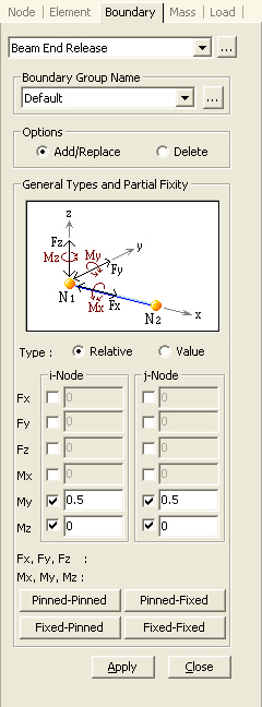
The following buttons simplify the individual
data entries described above:
To release the bending stiffness about the element's local y- and z-axes
at both ends
To release the bending stiffness about the element's local y- and z-axes
at N1 end
To release the bending stiffness about the element's local y- and z-axes
at N2 end
To restore all the end release conditions at both ends to fixed conditions