User Coordinate System
| ||||||
|
| ||||||
|
| ||||||
|
Define the User Coordinate System (UCS).
Most structures in practice are composed of a combination of many different plane frames and modules of similar geometric characteristics. Each plane frame and modular unit can be singled out in a given coordinate system apart from the Global Coordinate System. This local coordinate system is conveniently selected to simplify the process of geometry generation.
The User Coordinate System is referred to as the coordinate system set up by the user to ease the modeling task.
Use also
In addition, the use of UCS x-y plane in conjunction with the use of grids to place the grid points of grid lines provides an effective modeling environment. | ||||||
|
| ||||||
|
| ||||||
|
| ||||||
|
From the Main Menu select Model > User Coordinate System > X - Y Plane.
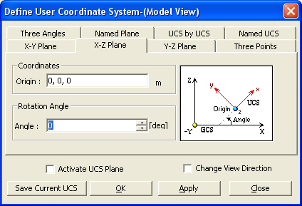
From the Main Menu select Model > User Coordinate System > X - Z Plane.
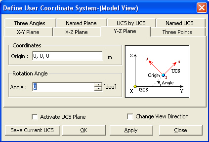
From the Main Menu select Model > User Coordinate System > Y - Z Plane.
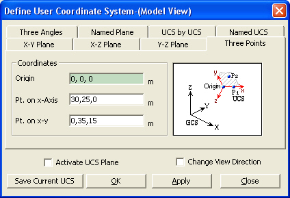
From the Main Menu select Model > User Coordinate System > Three Points.
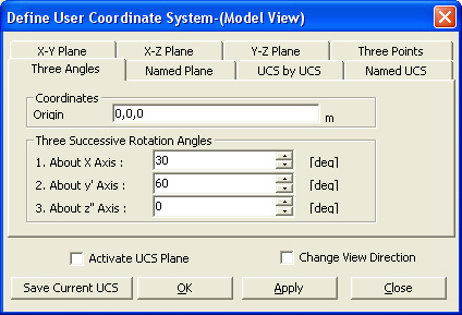
From the Main Menu select Model > User Coordinate System > Three Angles.
From the Main Menu select Model > User Coordinate System > Named Plane.
From the Main Menu select Model > User Coordinate System > UCS by UCS.
From the Main Menu select Model > User Coordinate System > Named UCS.
Select Geometry > User Coordinate System > X - Y Plane in the Menu tab of the Tree Menu.
Select Geometry > User Coordinate System > X - Z Plane in the Menu tab of the Tree Menu.
Select Geometry > User Coordinate System > Y - Z Plane in the Menu tab of the Tree Menu.
Select Geometry > User Coordinate System > Three Points in the Menu tab of the Tree Menu.
Select Geometry > User Coordinate System > Three Angles in the Menu tab of the Tree Menu.
Select Geometry > User Coordinate System > Named Plane in the Menu tab of the Tree Menu.
Select Geometry > User Coordinate System > UCS by UCS in the Menu tab of the Tree Menu.
Select Geometry > User Coordinate System > Named UCS in the Menu tab of the Tree Menu.
Click
Click
Click
Click
Click
Click
Click
Click | ||||||
|
| ||||||
|
| ||||||
|
Select a desired tab in the dialog box and enter the related data.
Activate UCS Plane Activate the UCS x-y plane including the
UCS origin point. Use
Change View Direction
Automatically change the View Point to view the model from the UCS (+)z-direction.
|


 X - Y
X - Y X - Z
X - Z Y - Z
Y - Z Three Points
 Three Angles
 Named Plane
 Set UCS by Current UCS
 Named UCS
 Origin
|
|
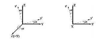
(a) Rotation about the GCS X-axis by AX angle
|
|
|
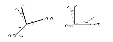
(b) Rotation about the modified y'-axis by AY angle (y'-axis defined by step a)
|
|
|
(c) Rotation about the modified z"-axis by AZ angle
|
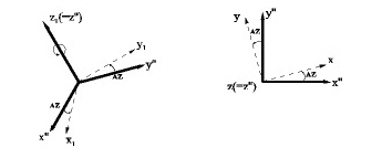
Definition of UCS (Three Angles)
 Named Plane tab
Define the UCS x-y plane by selecting a plane defined by Model > Named Plane.
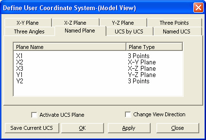
Named Plane dialog box
UCS by UCS tab
Define the UCS by modifying the currently defined UCS.
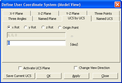
UCS by UCS dialog box
x Rot: Angle of rotation about the current UCS x-axis
y Rot: Angle of rotation about the current UCS y-axis
z Rot: Angle of rotation about the current UCS z-axis
Origin Point: Coordinates of the new UCS origin point relative to the current UCS
Named UCS tab
Access and apply a UCS previously saved.
To save the current UCS click  at the bottom of the dialog box
UCS Name
Name of saved UCS
Origin Point
Origin coordinates of the new UCS (in GCS)
ux: Direction vector of the new UCS in x-dir. (in GCS)
uy: Direction vector of the new UCS in y-dir. (in GCS)