Wind Loads
|
|
|
|
|
|
In MIDAS/Gen, the automatic data entry of wind loads according to various standards is applicable for common buildings where each story can be defined and can reasonably act as a rigid diaphragm. The following procedure is observed :
The structure must be modeled so that the gravity acts in the direction opposite to the GCS Z-direction.
When the ground level is entered, the parts below this level are considered as underground stories and neglected in the wind load calculation. If the ground level is not specified, the lowest part of the modeled structure is assumed to be the ground level by default.
It is recommended that
Once the floor diaphragm is defined in Story, the X-, Y-displacement degrees-of-freedom and the rotational degree-of-freedom about the Z-axis between all the nodes on the plane (plane parallel to the GCS X-Y plane) are constrained.
In addition, a part or all of the constrained nodes can be separated from the rigid floor diaphragm using Floor Diaphragm Disconnect.
[Built-in wind load calculation standards in MIDAS/Gen]
IBC 2000 (ASCE7-98): International Building Code 2000
UBC (1997): UBC 97 standards
ANSI (1982): ANSI standards
NBC (1995): National Building Code of Canada
Eurocode-1 (1992): Basis of Design and Actions on Structures
BS6399 (1997): British Standard 6399 Loading for buildings
IS875(1987): Indian Standard
Taiwan (2002): Taiwan Building Code
(available upon request)
Japan (Arch, 2004): Loading Specifications and Commentaries for Buildings
Japan (Arch, 2000): Loading Specifications and Commentaries for Buildings
Japan (1987): Loading Specifications and Commentaries for Buildings
KBC (2008): Korea Building Code 2008
Korean (Arch, 2000): Buildings loading criteria and commentaries
Korean (Arch, 1992): Regulations related to structural criteria for buildings
China (GS50011-2001): Code for Seismic Design of Building
Once the data required for the calculation
of wind loads are defined, auto-calculate wind loads for each story in
connection with the story data generated in Story. Use [Wind
load generation...]
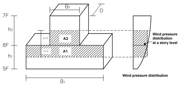
1) Wind load calculation If a floor area changes at a particular story level, the area subject to wind pressure is based on the sum of (A1=B1*h1/2) and (A2=B2*h2/2) relative to the corresponding story level. [Details...]
Fig. 1 Elevation
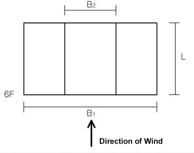
Fig. 2 Plan
2) External Pressure Coefficient Based on L/B2 for the upper portion and L/B1 for the lower portion
3) Design Pressure Actual distribution of the wind pressure is parabolic, but MIDAS/Gen expresses it in a stepped distribution because the design pressure is taken at the story levels as per Fig. 2. |
|
|
|
|
|
|
|
From the Main Menu select Load > Wind Loads.
Select Static Loads > Wind Loads in the Menu tab of the Tree Menu. |
|
|
|
|
|
Access Wind Loads to activate the dialog
box defining the wind loads. Click
Add/Modify Wind Load Code dialog box
|
|
|
 be
used to auto-generate the data necessary for the stories and the application
of wind loading. Where openings exist at a particular story, adjust the
width of the wind pressure area.
be
used to auto-generate the data necessary for the stories and the application
of wind loading. Where openings exist at a particular story, adjust the
width of the wind pressure area. to
verify the auto-calculated wind loads.
to
verify the auto-calculated wind loads.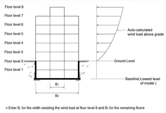
 to display the dialog
box shown below.
to display the dialog
box shown below.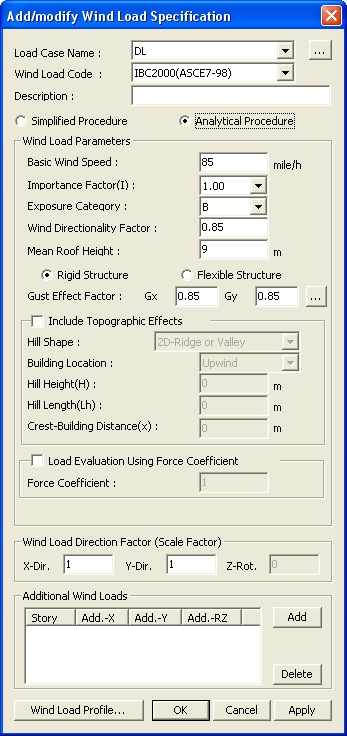
 Load Case Name
 to the right to enter or modify
new load cases.
to the right to enter or modify
new load cases. : Calculate Gust Response
Factors
: Calculate Gust Response
Factors
 to enter the stories
to apply additional wind loads and the magnitudes for each direction.
to enter the stories
to apply additional wind loads and the magnitudes for each direction. : Display Tables and Graphs
in a spreadsheet form for each loading direction and component of the
auto-calculated wind loads.
: Display Tables and Graphs
in a spreadsheet form for each loading direction and component of the
auto-calculated wind loads. : Display a spreadsheet Text
Output file showing the wind load calculation process.
: Display a spreadsheet Text
Output file showing the wind load calculation process.  : Apply the auto-calculated
wind loads to the model.
: Apply the auto-calculated
wind loads to the model.