Pressure Loads
| ||
|
| ||
|
| ||
|
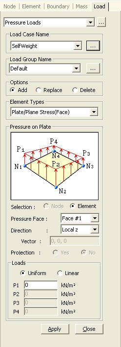
Apply pressure loads to the faces or edges of plate, plane stress, plane strain, axisymmetric or solid elements. Modify or delete previously entered loads.
The pressure loads are entered as either a uniform pressure or a linearly distributed pressure. The pressure is then converted into equivalent nodal forces in the program.
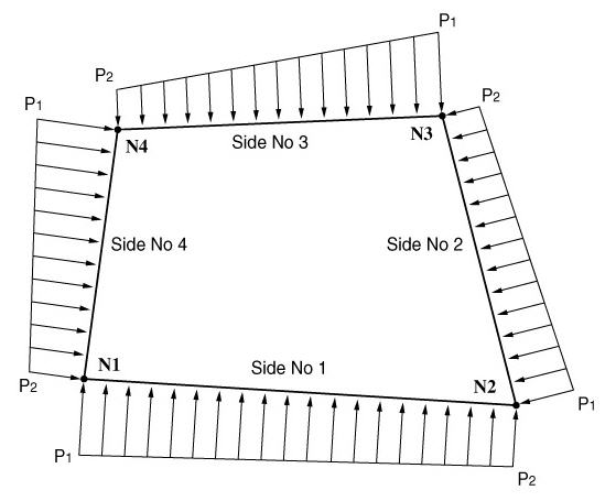
The pressure loads for plate or plain stress elements are entered with respect to the GCS or the element local coordinate system. The direction of the loading applied to the faces coincides with an axis of the given coordinate system. In the case of pressure loads applied to the edges, the loading directions are perpendicular to the edges in the plane of elements. Pressure loads acting towards the elements retain the positive sign (+). Pressure loads acting on the edges are expressed as loads per unit length.
The pressure loads acting on the edges of plane strain and axisymmetric elements are entered perpendicular to the edges. The positive direction (+) refers to loadings applied towards the element edges. In addition, the pressure area is obtained by multiplying the element length by the thickness. Again, the loading is applied per unit length.
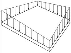
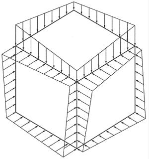
The direction of pressure loads applied to solid elements is perpendicular to the faces. The positive direction (+) refers to loadings applied towards the element faces. The loading direction away from the faces retains the negative sign (-). | ||
|
| ||
|
| ||
|
| ||
|
From the Main Menu select Load > Pressure Loads.
Select Static Loads > Pressure Loads in the Menu tab of the Tree Menu. | ||
|
| ||
|
| ||
| ||
|
|
 Load
Case Name
Load
Case Name to the right to enter, additional load cases and modify or
delete existing load cases.
to the right to enter, additional load cases and modify or
delete existing load cases. Vector