Combinations
| |||||||||||||||||||||||||||||||||||||||||||||||||||||||||||||||||||||||||||||||||||||||||||||||||||||||||||||||||||||||||||||||||||||||||||||||||||||||||||||||||||||||||||||||||||||||||||||||||||||||||||||||||||||||||||||||
|
| |||||||||||||||||||||||||||||||||||||||||||||||||||||||||||||||||||||||||||||||||||||||||||||||||||||||||||||||||||||||||||||||||||||||||||||||||||||||||||||||||||||||||||||||||||||||||||||||||||||||||||||||||||||||||||||||
|
| |||||||||||||||||||||||||||||||||||||||||||||||||||||||||||||||||||||||||||||||||||||||||||||||||||||||||||||||||||||||||||||||||||||||||||||||||||||||||||||||||||||||||||||||||||||||||||||||||||||||||||||||||||||||||||||||
|
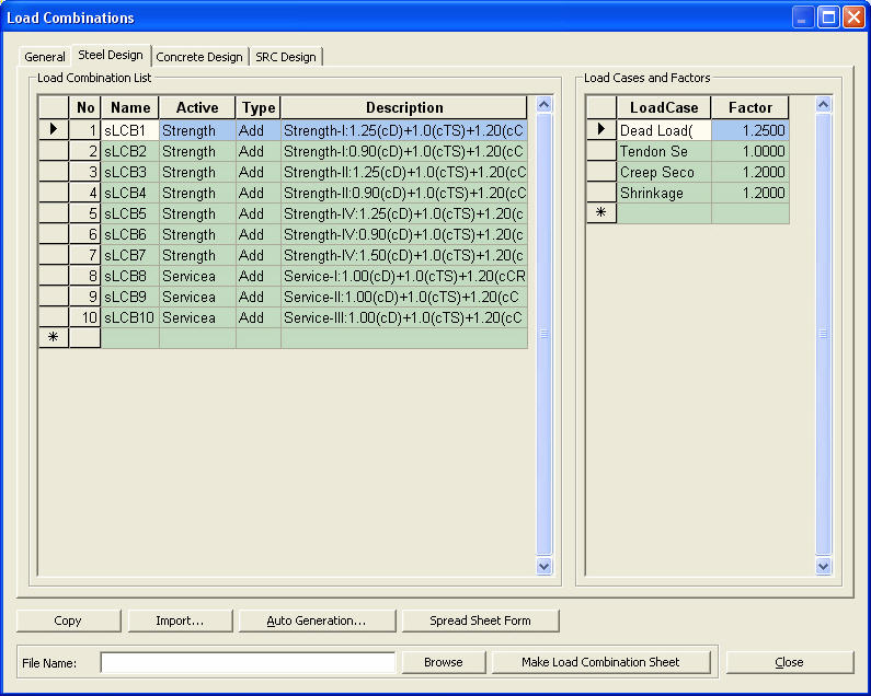
Enter the load combination cases to combine the results of static, construction stage, moving load, response spectrum and dynamic time history analyses.
MIDAS/Gen supports the following 5 types of dialog box tabs for load combinations.
Combine unit load cases to evaluate serviceability or analysis results irrespective of design codes.
Enter the load combinations for designing steel framing members according to the steel design codes.
Enter the load combinations for designing RC members according to the RC design codes.
Enter the load combinations for designing SRC members according to the SRC design codes.
Enter the load combinations for designing piles and footings. | |||||||||||||||||||||||||||||||||||||||||||||||||||||||||||||||||||||||||||||||||||||||||||||||||||||||||||||||||||||||||||||||||||||||||||||||||||||||||||||||||||||||||||||||||||||||||||||||||||||||||||||||||||||||||||||||
|
| |||||||||||||||||||||||||||||||||||||||||||||||||||||||||||||||||||||||||||||||||||||||||||||||||||||||||||||||||||||||||||||||||||||||||||||||||||||||||||||||||||||||||||||||||||||||||||||||||||||||||||||||||||||||||||||||
|
| |||||||||||||||||||||||||||||||||||||||||||||||||||||||||||||||||||||||||||||||||||||||||||||||||||||||||||||||||||||||||||||||||||||||||||||||||||||||||||||||||||||||||||||||||||||||||||||||||||||||||||||||||||||||||||||||
|
| |||||||||||||||||||||||||||||||||||||||||||||||||||||||||||||||||||||||||||||||||||||||||||||||||||||||||||||||||||||||||||||||||||||||||||||||||||||||||||||||||||||||||||||||||||||||||||||||||||||||||||||||||||||||||||||||
|
From the Main Menu select Results > Combinations.
Select Results > Combinations in the Menu tab of the Tree Menu.
Shortcut key : [Ctrl]+[F9] | |||||||||||||||||||||||||||||||||||||||||||||||||||||||||||||||||||||||||||||||||||||||||||||||||||||||||||||||||||||||||||||||||||||||||||||||||||||||||||||||||||||||||||||||||||||||||||||||||||||||||||||||||||||||||||||||
|
| |||||||||||||||||||||||||||||||||||||||||||||||||||||||||||||||||||||||||||||||||||||||||||||||||||||||||||||||||||||||||||||||||||||||||||||||||||||||||||||||||||||||||||||||||||||||||||||||||||||||||||||||||||||||||||||||
|
| |||||||||||||||||||||||||||||||||||||||||||||||||||||||||||||||||||||||||||||||||||||||||||||||||||||||||||||||||||||||||||||||||||||||||||||||||||||||||||||||||||||||||||||||||||||||||||||||||||||||||||||||||||||||||||||||
|
Load Combinations dialog box
The entry methods are similar for each dialog box. Refer to Usage of Table Tool and enter as follows:
Enter the load combination cases by the following 4 methods:
1. The user directly specifies the load combinations Directly enter the following basic items necessary to define load combinations in the Load Combination List.
No: Numbers are sequentially and automatically assigned in the order of the load combination entries.
Name: Enter the load combination name.
Note
Dead Load (CS): Dead load including Self Weight included in construction stages
Erection Load (CS): Erection load defined by Load Cases to be Distinguished from Dead Load for CS Output of Construction Stage Analysis Control
Tendon Primary (CS): Analysis results due to prestressing forces in tendons
Tendon Secondary (CS): Indeterminate forces resulting from indeterminate condition of the structure
Creep Primary (CS): Results the (imaginary) loads causing creep strain
Creep Secondary (CS): Real member forces resulting from creep strain due to indeterminate structure
Shrinkage Primary (CS): Results for the (imaginary) loads causing shrinkage strain
Shrinkage Secondary (CS): Real member forces resulting from shrinkage strain due to indeterminate structure
Summation (CS): Summation of the results of all the cases above
Note
Active: Specify Active if the corresponding load combination is applied in design.
Inactive: The corresponding load combination is not applied in the post-processing mode.
Active: The corresponding load combination is applied in the post-processing mode. (General tab)
Strength/Stress: The corresponding load combination is applied in the post-processing mode (Concrete Design tab) except for the serviceability check (crack and fatigue checks).
Serviceability:
The corresponding load combination is applied in the post-processing mode
(Concrete Design tab) except for the auto-design and strength check of
beam members.
Type: Assign the combination types for analysis results.
Add: Linear combination of analysis results L1 + L2 + ... + M1 + M2 + ... + S1 + S2 + ...+ (R1 + R2 + ...) + T + LCB1 + LCB2 + ... + ENV1 + ENV2 + ...
Envelope: Maximum, minimum and maximum of absolute values for individual analysis results
CBmax: Max (L1, L2, ..., M1, M2, ..., S1, S2, ...,R1, R2, ..., T, LCB1, LCB2, ..., ENV1, ENV2, ...)
CBmin: Min (L1, L2, ..., M1, M2, ..., S1, S2, ...,R1, R2, ..., T, LCB1, LCB2, ..., ENV1, ENV2, ...)
CBall: Max (|L1|, |L2|, ..., |M1|, |M2|, ..., |S1|, |S2|, ..., |R1|, |R2|, ..., |T|, |LCB1|, |LCB2|, ..., |ENV1|, |ENV2|, ...)
Note
ABS: Linear combination of the absolute values of analysis results
|L1| + |L2| + ... + |M1| + |M2| + ... + |S1| + |S2| + ...+ (|R1| + |R2| + ...) + |T| + |LCB1| + |LCB2| + ... + |ENV1| + |ENV2| + ...
SRSS: Linear combination of the SRSS (Square Root of Sum of the Squares) of response spectrum analysis results and other analysis results
[L12 + L22 + ... + M12 + M22 + ... + S12 + S22 +...+(R12 + R22 +...) + T2 + LCB12 + LCB22 + ... + ENV12 + ENV22 + ...]½
where, L: static analysis results for a unit load case �� scale factor M: static analysis results for a moving load case �� scale factor S: static analysis results for a settlement load case �� scale factor R: dynamic analysis results for a Response Spectrum case �� scale factor T: dynamic analysis results for a Time History Analysis case �� scale factor LCB: Analysis results for a predefined load combination �� scale factor ENV: Analysis results for a predefined envelop conditions �� scale factor
Note
1
Note
2
Note
3
Description: Short descriptions for the load combinations Enter the unit load cases and the corresponding scale factors included in the relevant load combination as many times as desired.
Load Case: Select the unit load cases from the load case list or the load combinations defined earlier.
Factor: Enter the load (scale) factors corresponding to the selected unit load cases or load combinations.
2. Select built-in design standards to automatically generate load combinations Click
Note
Auto Generation Dialog box
Add : Add the generated load combinations to the previously defined load combinations
Replace : Replace the previously defined load combinations with the generated load combinations
Add Envelope: Envelope of load combinations is auto-generated. This is applicable in the General tab only.
Code Selection
Steel: Design code for structural steel
Concrete: Design code for reinforced concrete
SRC: Design code for steel-reinforced concrete composite sections
Footing: Design code for reinforced concrete footings
Design Code : Select the design code to be used for the auto-generation of load combinations (Refer to Note for design load combinations for different codes)
Scale Up Factor : Enter the seismic load scale factor where the seismic load is considered by the response spectrum analysis
Manipulation of Construction Stage Load Case: Select a method of auto-generating load combinations when Construction Stage Analysis has been performed.
Note
ST Only: This option generates load combinations using only (general) static load cases (DL (ST), LL (ST)).
CS Only: This option generates load combinations using only construction stage load cases (DL (CS), LL (CS)).
ST+CS: This option generates load combinations using both (general) static load cases and construction stage load cases together.
Note
If we wish to reflect the results of the construction stage analysis into design, we need to select the CS Only option. If we select the ST+CS option, the load cases used in the construction stage analysis are accounted for twice in the form of both static load case type and construction stage load case type. If we select the ST Only option, only the static analysis results are included in the design load combinations in which case the construction stage analysis results will be excluded from the design load combinations.
When we use the construction stage load (CS) type in a construction stage analysis, only the CS type is created after the analysis. In such a case, we need to select the CS Only option. By the same token, we cannot select the ST Only or ST+CS option because ST type loads do not exist.
When we distinguish the ST type and CS type loads in the preparation of data for a construction stage analysis, we need to select the ST+CS option to account for all the loads input in the model.
Consider Orthogonal Effect: When seismic forces are applied in two orthogonal directions, the combination effect is considered.
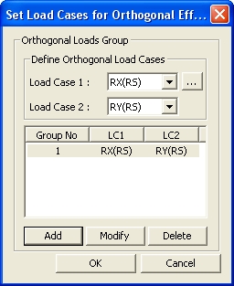
Set Load Cases for Orthogonal Effect: Set 2 load cases, which will be considered for Orthogonal Effect.
Set Load Cases for Orthogonal Effect dialog box
100% vs. 30%: 100% of seismic load in one direction and 30% of seismic load in the orthogonal direction are summed in absolute values.
SRSS (Square Root of Sum of Square): 100% of seismic loads in both directions are combined in SRSS.
Note
1
Note 2
Coefficients for Serviceability: Define the Live Load and Wind Load factors for serviceability check (This becomes activated only when Eurocode 2 or Eurocode 3 is selected).
Note
1
Note
2
Note 3 For the procedures to be followed to check serviceability as per Eurocode 2 and Eurocode 3, refer to [Procedure for Serviceability Check as per Eurocode 2] in Design > Concrete Code Check > Beam Checking and [ Procedure for Serviceability Check as per Eurocode 3 ] in Design > Steel Code Check, respectively.
3. Enter or modify the load combinations in a Spread Sheet form table Click
4. Import a load combination (fn.lcb) file to generate load combinations Click
The fn.LCB file type is as follows:
Sequential number, combination method, unit load case i, load factor i, unit load case j, load factor j, ..., load combination k, load factor k, load combination l, load factor l
Examples) 1, , 1, 1.0, 2, 1.0 2, , 1, 1.4, 2, 1.7
Note 1 Allow one or more spaces between the commas of Load Combination No. When adding some load combinations to existing load combinations using Import, do not use the same Load Combination No. as that of the existing Load Combination. (Error Message will be displayed)
Note 2 For the method of calculating principal stresses, effective stresses and maximum shear stresses for each load combination type, refer to the explanations at the bottom of the page.
Select the load combination to be modified in the load combination list and modify the entry.
Select the load combination to be copied
in the load combination list and click
Select the load combinations to be deleted in the load combination list and click the Delete key.
Note
1. Available Force Components
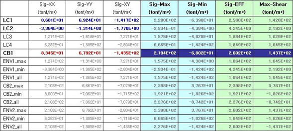
2. Examples - for each Load Case/Load Combination
a. The load combination CB1 is an Add type and the types of displayed results are identical to those of general load cases.
b. ENV1 and 2 are Envelope type load combinations and the results are classified into Max, Min and All.
c. CB2 is an Add type load combination but includes an Envelope type load combination ENV1. Therefore, the results are classified into Max, Min and All.
d. "Max" displays the maximum of the results, "Min" displays the minimum and "All" displays the absolute maximum. Check the option in the Preference menu to produce the "All" type results with signs instead of the absolute values.
3. Calculation of CB1 stresses (Add type load combination that includes general load cases)
�� CB1 = LC1 + LC2 a. Principal stress: Add the stresses of all load cases for each stress component and then recalculate the principal stress based on the sum of the stresses for each stress component.
b. Sig-EFF & Max-Shear: Calculate based on the principal stress calculated from above (*Note: The principal stress, effective stress and maximum shear stress of CB1 are not calculated simply by summing the results of LC1 and LC2.)
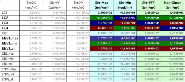
4. Calculation of ENV1 stresses (Envelope type load combination that includes general Load Cases or Add type load combinations)
�� ENV1 = Envelope (LC2, LC3, LC4) Principal stress & Sig-EFF & Max-Shear: Display the maximum, minimum and absolute maximum values among the principal stresses of LC2, LC3 and LC4. The same goes for Sig-EFF & Max-Shear.
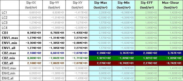
5. Calculation of CB2 stresses (Add type load combination that includes Envelope type load combinations)
�� CB2_max = CB1+ENV1_max CB2_min = CB1+ENV1_min CB2_all = CB1+ENV1_all
a. Based on the stresses of 'CB2_max' 'CB2_min' and 'CB2_all' for each stress component, Sig-Max, Sig-Min, Sig-EFF and Max-Shear are recalculated.
b. CB2 load combination includes Envelope type load combinations, but it is an Add type load combination. First, calculate the sum of the stresses of all load cases for each stress component and recalculate the principal stress, effective stress, etc based on the sum of the stresses for each stress component.
6. Calculation of ENV2 stresses (Envelope type load combination that includes Envelope type load combinations) - The calculation method is identical to that for ENV1.
�� ENV2_max = MAX[LC4, CB1, max(CB2)] ENV2_min = MIN[LC4, CB1, min(CB2)] ENV2_all = MAX[abs(LC4), abs(CB1), all(CB2)]
Note 2. The 'all' condition of an Envelope type load combination or an Add type load combination that includes an Envelope type load combination produces the maximum of absolute values. Whether to produce the values with signs or without signs can be determined from the Tools>Preferences.
| |||||||||||||||||||||||||||||||||||||||||||||||||||||||||||||||||||||||||||||||||||||||||||||||||||||||||||||||||||||||||||||||||||||||||||||||||||||||||||||||||||||||||||||||||||||||||||||||||||||||||||||||||||||||||||||||
|
| |||||||||||||||||||||||||||||||||||||||||||||||||||||||||||||||||||||||||||||||||||||||||||||||||||||||||||||||||||||||||||||||||||||||||||||||||||||||||||||||||||||||||||||||||||||||||||||||||||||||||||||||||||||||||||||||
 To enter
new or additional load combinations
To enter
new or additional load combinations at the bottom of
the load combinations dialog box. Select the following items in the displayed
load combination auto-generation dialog box. If
at the bottom of
the load combinations dialog box. Select the following items in the displayed
load combination auto-generation dialog box. If  is clicked,
the load combinations are automatically entered as per the design code
based on the user-defined unit load cases.
is clicked,
the load combinations are automatically entered as per the design code
based on the user-defined unit load cases.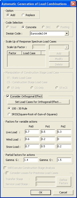
 in the load combinations
dialog box to convert the data into a spreadsheet form table arranging
the unit load cases in rows. Enter or modify the items mentioned in Method
1 to add or modify unit load cases.
in the load combinations
dialog box to convert the data into a spreadsheet form table arranging
the unit load cases in rows. Enter or modify the items mentioned in Method
1 to add or modify unit load cases. in the load combinations
dialog box to display the dialog box that imports the load combination
files. Select a file containing previously entered load combinations.
in the load combinations
dialog box to display the dialog box that imports the load combination
files. Select a file containing previously entered load combinations. : Select desired load combinations
from the General tab and a design tab to the right of the [Copy into]
button, and click the [Copy into] button. Only the selected load combinations
are copied to the corresponding design tab. This functionality can be
used only under the General tab.
: Select desired load combinations
from the General tab and a design tab to the right of the [Copy into]
button, and click the [Copy into] button. Only the selected load combinations
are copied to the corresponding design tab. This functionality can be
used only under the General tab. : The load combinations in
the currently activated tab can be output in a text file (*.lcp).
: The load combinations in
the currently activated tab can be output in a text file (*.lcp). .
. Revision of V.7.6.1