A single Member can be assigned when the member is consisted of a number
of line elements (beam elements or truss elements).
From the Main
Menu select Design
> General Design Parameter > Member Assignment.
From the Menu
tab of the
Tree Menu select Design
> General Design Parameter > Member Assignment.
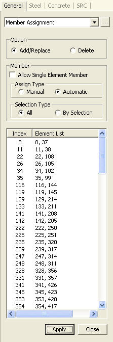
Select the corresponding elements to be assigned
as a member, and enter the following
Option
Add/Replace:
A new Member can be defined or an existing Member can be revised.
Delete:
Assigned members can be deleted. You may either select the Members to
be deleted from the model window or the Element List window.
Member
Allow Single
Element Member: Check on to permit a single element to be assigned
as a member.
Assign Type
Manual:
The User defines Members directly.
Automatic:
The program defines Members automatically.
Selection Type
All:
All is selected if all the elements are to be assigned Members. This becomes
activated if Automatic is selected in Assign Type.
By Selection:
A Member is assigned to selected elements.
: Selected elements
are assigned a Member.
: Input Dialog Bar is
closed.
Note
1
When a number of elements are assigned a single Member, the Member number
retains the smallest element number. That element then becomes the representative
element. All design parameters for the Member must be input for the representative
element.
Note
2
If the elements to be assigned a Member retain different material and section
properties, or the directions of the node connections are different, a
Member can not be assigned.
Note 3
The design parameters, Effective Length Factor (K), Equivalent Moment correction
Factor (Cm), Moment Magnifier (B1/δb,B2/δs) and Limiting Slenderness Ratio
are taken from the representative element, and Unbraced Length (L,Lb)
is taken from each element.
 Option
 : Selected elements
are assigned a Member.
: Selected elements
are assigned a Member. : Input Dialog Bar is
closed.
: Input Dialog Bar is
closed.