Use this function to select the design code to apply for the strength
verification of steel members and specify the lateral bracing condition
of the structure's horizontal members (beams and girders).
From the Main
Menu select Design
> Steel Design Parameter > Design Code.
From the Menu
tab of
the
Tree Menu select Design
> Steel Design Parameter > Design Code.
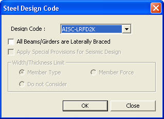
The following dialog box is used for data
entry:
Steel Design Code dialog box
Design Code
Steel design code (refer to Note 1)
All Beams/Girders are Laterally Braced
Specify the lateral brace condition to the
horizontal members (beams and girders) of the structure to be designed
(refer to Note
2).
Apply Special Provisions
for Seismic Design
Not available
: Enter the selection
and close the dialog box.
: Do not enter the data
or the selection and close the dialog box.
- Load and Resistance Factor Design, the American
Institute of Steel Construction (AISC-LRFD 2k & 93)
- Allowable Stress Design, the American
Institute of Steel Construction (AISC-ASD89)
- British Standard, Structural use of
steelwork in building (BS5950-90)
- EN 1993-1-1:2005 Eurocode3, Design of
Steel Structures Part 1.1 (Eurocode3:05)
- ENV 1993-1-1:1992 Eurocode3, Design of Steel
Structures Part 1.1 (Eurocode3)
- Canadian Standards Association, Limit States
Design of Steel Structures (CSA-S16-01)
- American Iron and Steel Institute, Cold-Formed
Steel Design, 1986 (AISI-CFSD86)
(available upon request)
- The Architectural Institute of Japan (AIJ-ASD02)
- The Architectural Institute of Korea (AIK-ASD83)
- The Specifications for Roadway Bridges and
Steel Bridges of the Korean Society of Civil Engineers (KSCE-ASD96)
- The Steel Structures Limit-State Design
Criteria of the Architectural Institute of Korea (AIK-LSD97)
- The Cold-Formed Steel Design of the Architectural
Institute of Korea(AIK-CFSD98)
- China Standard(GBJ17-88)
- Indian Standard(IS800-1984)
- Indian Standard(IS800-2007)
Note
2
When the top compression flanges of the steel girders or beams are connected
to the concrete floor by welded metal decks and/or shear connectors, it
is assumed that all the members are laterally braced. If this item is
selected, the Laterally Unbraced Length (Lb) field is deactivated in the
"Unbraced Length (L,Lb)" Dialog Bar and Lb = 0 is applied to
all the members.
(Refer to "Unbraced
Length (L,Lb)")
 Design Code
 : Enter the selection
and close the dialog box.
: Enter the selection
and close the dialog box. : Do not enter the data
or the selection and close the dialog box.
: Do not enter the data
or the selection and close the dialog box. Revision of Ver.7.6.1