The pile element
behavior is the interfacial behavior between the parent
element and pile elements such as a beam or a truss. The
interfacial behavior for a pile can divided into 2 normal
direction behavior and 1 tangent direction behavior. Like
the interface element, the shear/vertical stiffness is
defined for simulation of interface behavior but here,
it is assumed that the 2 normal direction (vertical) motions
undergoes identical rigid body motion as the parent element
and the tangent direction (shear) behavior undergoes nonlinear
elastic motion.
The
pile tip element behavior is the interfacial behavior
between the parent element and the 1 tip of the pile element.
It is assumed that the normal direction behavior with
respect to the element coordinate axis at the pile tip
undergoes identical rigid body motion as the parent element
and the tangent direction behavior undergoes nonlinear
elastic motion. For the pile element, it is assigned either
multiple curves as a nonlinear material model or a value
for fully plastic behavior.
Pile
and pile tip elements express nonlinear behavior through
default stiffness as well as bearing power or ultimate
strength. The nonlinear behavior can be defined by functions
and a 3D table is supported for piles to define different
function for different depths.
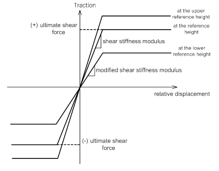
When
defining the shear stiffness of the pile using yield strength,
assume that the slope and yield strength undergoes fully
elasto-plastic behavior depending on height as shown below.
The user can also define the strain-frictional force relationship
curve for different heights when defining the stiffness
as a function.

<Relative displacement-Frictional
force relationship>
 
Input
a certain coefficient for the normal direction. The nonlinear
analysis is analyzed linearly. For the shear direction,
use the input coefficient and analyze if linear. For nonlinear
analysis, also consider the ultimate shear strength and
analyze as a fully plastic model. If the shear stiffness
is differs for each depth, a function must be used.
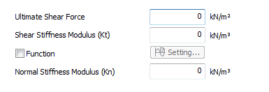
Ultimate
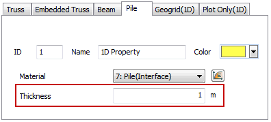
Shear Force : Input the ultimate shear resistance force(kN)
of the pile for a load in the axial direction in stress
units, by dividing it with the pile length(m) and pile
element thickness(m). The frictional force of the pile
is output as the force per unit length(kN/m) and the Ultimate
frictional force becomes the input [Ultimate shear force(kN/m2)
x Pile element thickness(m)].
Shear
Stiffness Modulus (Kt) : The slope of the linear section
of the friction stress(kN/m2)-relative displacement(m)
curve that has the units of kN/m3. When the analysis results
of the tangent direction frictional force(kN/m) and relative
displacement(m) of a pile is drawn with respect to the
applied load size, the graph has a linear slope(kN/m2)
until the ultimate frictional force and this becomes the
input [Shear stiffness modulus(kN/m3) x Pile element thickness(m)].
Function
: To specify the nonlinear elastic behavior in the tangent
direction, define the Friction stress(kN/m2)-Relative
displacement(m) curve for each depth, rather than entering
the Ultimate shear force and Shear stiffness modulus.
Normal
Stiffness Modulus (Kn) : The slope of the linear section
of the relationship graph between the ground resistance
to a horizontally applied force(kN), which is expressed
as stress by dividing it with the pile length(m) and pile
element thickness(m), and the relative displacement. It
is the same concept as the Lateral subgrade reaction modulus,
calculated from general p-y analysis. When the analysis
results of the tangent direction frictional force(kN/m)
and relative displacement(m) of a pile is drawn with respect
to the applied load size, it is the linear slope(kN/m2),
which can be expressed as the input [Shear stiffness modulus(kN/m3)
x Pile element thickness(m)].
When
using the Lateral subgrade reaction modulus formula proposed
by the design code, input the calculated coefficient into
the Normal Stiffness Modulus and the pile element thickness
can be input as a unit width(1m).

Because the pile size, length,
neighboring ground material properties all affect the
pile element parameters, it is ideal to use the results
of a loading test. However, if there are no test results,
the Ultimate Shaft Resistance, Lateral Subgrade Reaction
Modulus and End Bearing Capacity of a pile can be calculated
using the formulas proposed by the design code and the
neighboring ground parameters (unit weight, cohesion,
friction angle etc.).
1. Using loading
test results
For example, if a load of 1000kN
was found before failure from the pile loading test and
the pile length was 10m, the Ultimate shear force is [1000kN/10m/1m]
= 100kN/m2. Here, the 1m is the unit length of the input
pile element thickness.
The Shear stiffness modulus is
the slope of the linear section on the relationship graph
with relative displacement until the 1000kN load is applied.
If we assume that the relative displacement at 1000kN
is 0.01m, the Shear stiffness modulus becomes [100kN/m2
/ 0.01m] = 10000kN/m3.
2. Using the
Ultimate Shaft Resistance results
For each design code, various formulas
are suggested to predict the Ultimate bearing capacity
of a pile according to ground and pile section properties.
For example, if the calculated Ultimate shaft resistance
is 50kN/m2 and the Shaft surface area of the pile(equivalent
circumference) is 3m, input 50kN/m2 for the Ultimate shear
force and 3m for the Pile element thickness respectively,
or input 150kN/m2 for the Ultimate shear force and the
unit length of the Pile element thickness 1m. The Pile
element length is automatically taken into account.
Because the load-relative displacement
has no relationship, if the allowable settlement is assumed
to occur at the Ultimate bearing capacity, the Shear stiffness
modulus applied to the analysis can be inferred with reference
to the allowable settlement. If the allowable settlement
is 0.025m for the example above, the Shear stiffness modulus
is [150kN/m2 / 0.025m] = 6000kN/m3. If the Pile element
thickness is 3m, entering [50kN/m2 / 0.025m] = 2000kN/m3
still gives the same results.
However, if a different numerical
value from the unit length is input for the Pile element
thickness, be aware that the same Normal stiffness modulus
is equally applied.
3. Applying
the interface Wizard interaction formula
Pile elements are also used to
estimate the ground-structure mutual behavior with interface
elements. Because the neighboring ground material has
a larger affect than the pile stiffness or sectional properties,
the shear/normal stiffness of the pile element can be
inferred using the interaction formula that calculates
the tangent/normal stiffness on the interface Wizard.
[Kn = Eoed,i
/ (L x tv) , Kt = Gi / (L x tv)]
Here,
Eoed,i = 2 x Gi x (1-νi)/(1-2 x νi)
(νi =Interface Poisson’s ration=0.45,
the interface is used to simulate the non-compressive
frictional behavior and automatically calculates using
0.45 to prevent numerical errors.)
tv = Virtual thickness (Generally
has a value between 0.01~0.1, the higher the stiffness
difference between ground and structure, the smaller the
value)
Gi = R x Gsoil (Gsoil = E/(2(1+
νsoil)), R = Strength Reduction Factor
The
general Strength reduction factor for structural members
and neighboring ground properties are as follows.
When inferring the shear/normal
stiffness of the pile using this method, the Ultimate
shear force can be found using the Shear stiffness modulus,
as calculated in example 2, and the allowable displacement
that is to be applied in the analysis.
Examples 2 and 3 are only acceptable
suggestions when the test results are not available. For
accurate behavior predictions, the load test must be conducted,
or the design parameters need to be computed through repeated
analysis. |


