Curve: Create Arc 2D
![]()
Function
Creates independent Arcs for edge type. Only applicable on the work plane. An arc is always drawn counterclockwise from the start point.
Call
Geometry > Curve > Create
on WP > Arc 
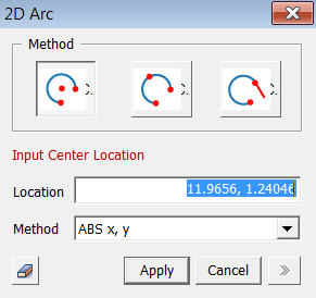
<Arc>
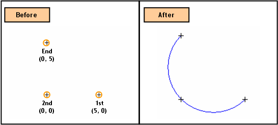
<Method>

The
Center [(Abs x, y)], Start [(Abs x, y), (Radius, Start Angle)] and End
[(Abs x, y), (Included Angle), (End Angle)] Locations are sequentially
specified.

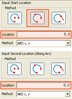
The
Start [(Abs x, y)], any point on the Arc [(Abs x, y)] and End [(Abs x,
y)] Locations are sequentially specified.

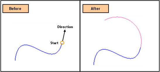
Create
an Arc whose Start Location [(Abs x, y)] is at an end of an existing edge
and tangent to the edge. The End Location [(Radius,
Included Angle)] is defined relative to the Start Location. The
new Arc exists as an independent edge, separated from the reference edge
from which the new Arc was created. Placing the
mouse closer to one end of an edge defines the coordinates of the Start
Location of the new Arc.
Location
Enter
the coordinates of the locations. The coordinates
are expressed in different forms noted below.
<Method of Entering Coordinates>
ABS x, y
Enter
2-D coordinates for an absolute location on the Work Plane.
Radius, Start Angle
Enter
a Radius and a rotational Angle (counterclockwise +) from the + X-direction
on the Work Plane.
Included Angle
Enter
an Angle of the Arc relative to the Start Location.
End Angle
Enter a rotational Angle (counterclockwise +) from the + X-direction on the Work Plane.
When entering coordinates using the mouse, the coordinates are automatically entered by left-clicking on the desired point, without having to press the [Apply] button. However, when coordinates are typed in, either [Enter] or [Apply] button needs to be pressed.
Notes
When 3-D coordinates are selected in 3-D space using Snap, the program will automatically project the point into 2-D coordinates of the Work Plane.