Curve: Create Circle 2D
![]()
Function
Create Circles of the edge type. It is only applicable on the Work Plane.
Call
Geometry > Curve > Create
on WP > Circle 
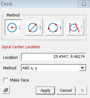
<Circle>
<Method>

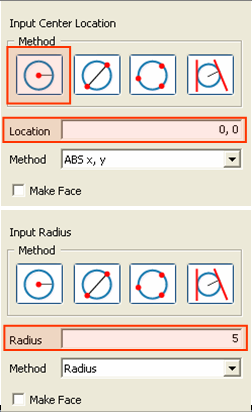
Create
a Circle by specifying its Center Location [(ABS x, y)] and Radius [(Radius)].

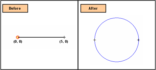
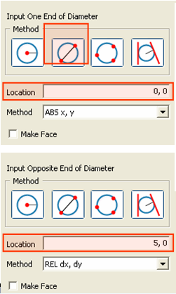
Create
a Circle by entering the coordinates of one end [(ABS x, y)] of a diameter
and the other end point [(ABS x, y), (REL dx, dy), (Length, Angle)].

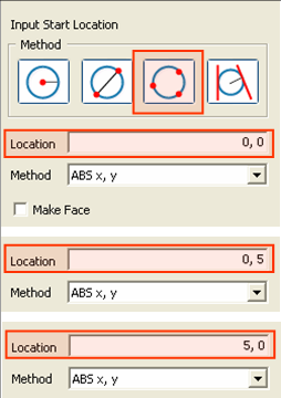
Create
a Circle by specifying the coordinates of three points [(ABS x, y)] on
the Circle.

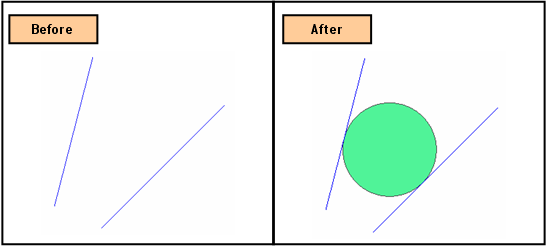
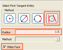
Create
a Circle, which is tangent to two selected edges and has a specified radius.
Enter a radius and then select two edges.
Location
Enter
the coordinates of the locations. The coordinates
are expressed in different forms noted below.
<Methods of Entering Coordinates>
ABS x, y
Enter
2-D coordinates for an absolute location on the Work Plane.
Radius
Enter
the Radius of a circle.
REL dx, dy
Enter
a distance relative to the Start Location on the Work Plane.
Length, Angle
Enter a relative distance from the Start Location and the rotational Angle (counterclockwise +) from the + X-direction on the Work Plane.
When we enter coordinates using the mouse, the coordinates are automatically entered by a left-click on the desired point, without having to press the Apply button. However, when coordinates are typed in, either the Enter key or the Apply button needs to be pressed.
Make Face
Create a Face using Plane Patch. This operation will not create a Circle of the edge type.
Notes
When 3-D coordinates are selected in 3-D space using Snap, the program will automatically project the point into 2-D coordinates of the Work Plane.