Modifier Feature: Offset
![]()
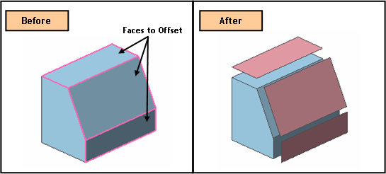
Function
Offset a Solid or Shell either entirely or partially to create a Shell.
Call
Geometry > Modifier Feature > Offset
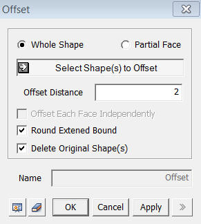
Whole Shape
Offset all the faces of a selected object by the same Offset Distance.
Select Shape(s) to Offset
Select Shapes(s) (Solid, Shell, Face) to be offset Offset.
<Offset>
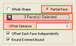
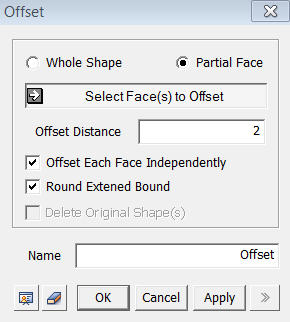
Partial Face
Offset only selected faces of the object. If a number of faces are selected, they are offset independently.
Select Face(s) to Offset
Select
faces (Face) to be offset.
Offset Distance
Specify
an Offset Distance.
Name
Enter the name of the Shell to be created by Offset.
Offset Each Face Independently
Offset
each selected face individually.
Round Extended Bound
This option is meaningful when offsetting a Whole Shape. After faces have been offset, this option rounds the unconnected parts of the offset faces.
Notes
The Offset command is executed with reference to each selected Face. When partial faces of a complex Shell are to be offset, it may create faces that are separated from one another. In such a case, the Offset operation cannot proceed unless both Offset Each Face Independently and Round Extended Bound options are used.
A positive value for the Offset Distance defines the direction of offset normal to the selected faces. Thus, it is inconvenient to preview the offset operation on each face individually. However, if a Shell is created using Sew or Fuse, the program adjusts the normal directions of the faces to a single consistent direction. Having a Shell helps us control the direction of Offset.