Surface: Imprint
![]()
Function
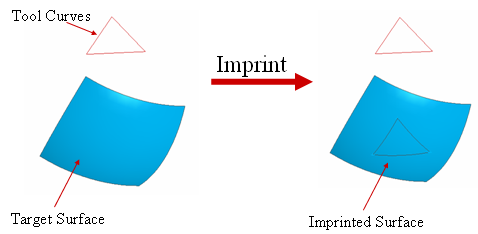
Project curves (Edge) or vertices onto a selected surface, and create internal objects of the surface using the projected curves (Edge) or vertices. These imprinted curves (Edge) or vertices will be taken into account when generating a mesh on the surface.
Call
Geometry > Surface > Imprint
Imprint Curve
Imprint
curves on selected surfaces.
Select Shape
Select
a shape, which includes the surfaces to be imprinted on.
Select Target Surface(s)
Among
the faces of the selected shape, select the target faces on which an Imprint
operation will be undertaken.
Select Tool Curve(s)
This is the input button used for the Imprint Curve operation. Select curves to be imprinted.
Direction Option
Specify
the direction in which the Tool Curves or the Tool Vertices will be projected
onto the Target Shape.
Direction
Specify
a direction (Datum Axis, Datum Plane, Face,
Edge).
2 Point Vector
Specify
the direction by a vector which is defined by selected 2 points. Snap
is applicable.
Point on Curve(Ratio)
Project
the Tool Curves or the Tool Vertices in the direction of the shortest
path from a point on a curve to the Target Surfaces.
Point
Project
the Tool Curves or the Tool Vertices in the direction of the shortest
path from a reference vertex to the Target Surfaces.
Direction of Shortest Path Line
Project the Tool Curves or the Tool Vertices in the directions of the shortest paths to the Target Surfaces.
Connect Two Vertices by Line
This option is only applicable when imprinting vertices. The Option joins the source vertices and the corresponding imprinted vertices.
<Imprint>
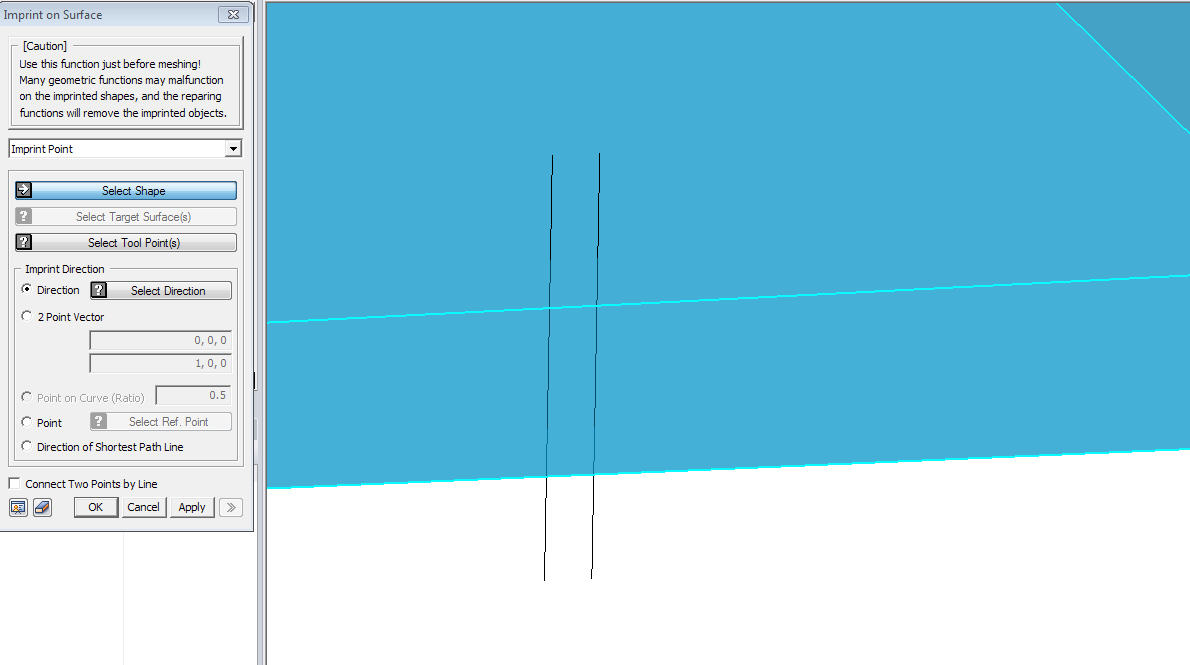
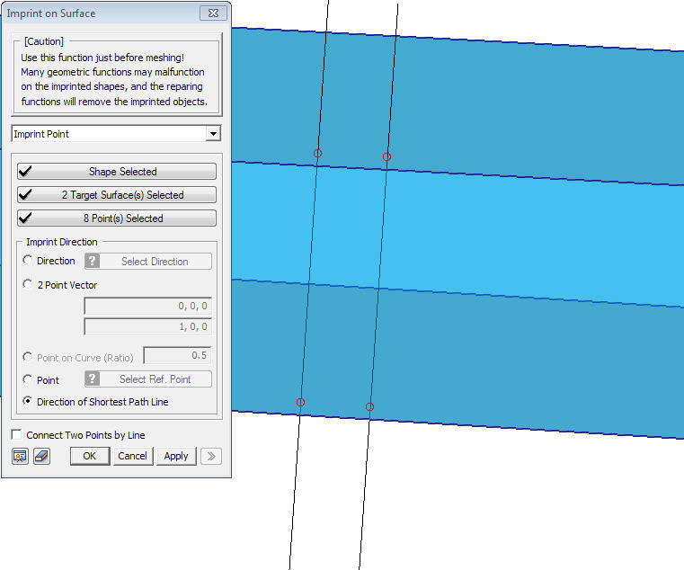
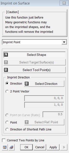
Imprint Point
Imprint
vertices on selected surfaces.
Select Shape
Select
a shape, which includes the surfaces to be imprinted on.
Select Target Surface(s)
Among
the faces of the selected shape, select the target faces on which an Imprint
operation will be undertaken.
Select Tool Point(s)
This
is the input button used for the Imprint Vertex operation. Select
vertices to be imprinted.
Direction Option
Specify
the direction in which the Tool Curves or the Tool Vertices will be projected
onto the Target Shape.
Direction
Specify
a direction (Datum Axis, Datum Plane, Face,
Edge).
2 Point Vector
Specify
the direction by a vector which is defined by selected 2 points. Snap
is applicable.
Point on Curve(Ratio)
Project
the Tool Curves or the Tool Vertices in the direction of the shortest
path from a point on a curve to the Target Surfaces.
Point
Project
the Tool Curves or the Tool Vertices in the direction of the shortest
path from a reference vertex to the Target Surfaces.
Direction of Shortest Path Line
Project the Tool Curves or the Tool Vertices in the directions of the shortest paths to the Target Surfaces.
Connect Two Vertices by Line
This option is only applicable when imprinting vertices. The Option joins the source vertices and the corresponding imprinted vertices.