Protrude Mesh: Extrude Mesh incomplete
![]()
Function
Extrude Mesh creates elements by extruding a node to a 1D element, a 1D element to a 2D element, a Edge to a 2D element, and a 2D element to a 3D element.
Call
Mesh > Protrude Mesh > Extrude
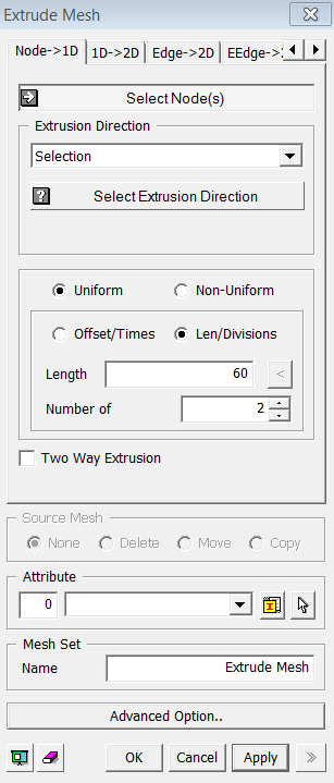
<Extrude Mesh : Node->1D>
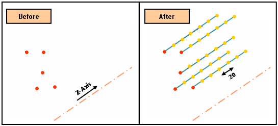
<Node -> 1D>: See its example
Select Node(s)
Select the nodes (Mesh, Node) that will be extruded.
Extrusion Direction
Selection
Select
an extrusion direction (Datum Axis, Datum
Plane, Face, Edge).
Offset Component
Using
the vector components, the selected nodes are extruded at a uniform offset
interval by the number of times specified.
2 Point Vector
Select a direction of extrusion by a vector which is defined by two specified points. The coordinates of 2 points may be specified using Snap.
Uniform
Extrude
the selected elements at a uniform distance by the number of times specified.
Offset
Enter
an offset distance for extrusion. If the selected direction has a finite
length, user can automatically input its length by pressing  button.
Number of Times
Enter
the number of offsets.
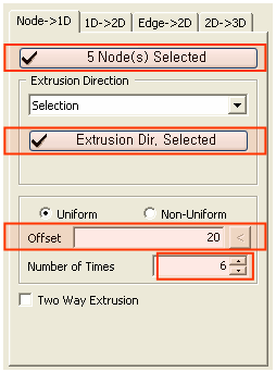
Non-Uniform
Extrude
the selected nodes by specifying non-uniform distances entered as a function.
Enter multiple distances separated by commas (,).
For repetition, use the input format as the number
of times @ distance. Example) 30,20,2@15,20
Two Way Extrusion
This option create the same mesh on the reverse side of specified direction.
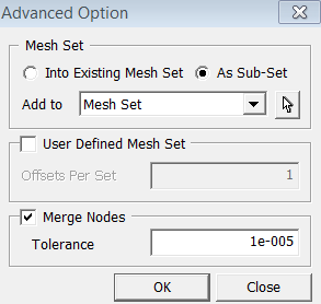
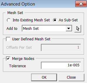
User Defined Mesh Set
User can specify the number of offsets per set. If one number has been entered, it will uniformly register generated mesh by the number of offsets. If more than one number has been entered, it will non-uniformly divide the Mesh Set by the given numbers. The sum of the numbers should not be greater than the total number of offsets.
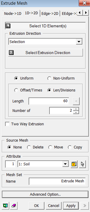
<Extrude Mesh : 1D->2D>
<1D -> 2D>: See its example
Select 1D-Element(s)
Select the 1D elements (Mesh, Element) that will be extruded.
Selection
Select
an extrusion direction (Datum Axis, Datum
Plane, Face, Edge).
Offset Component
Using
the vector components, the selected nodes are extruded at a uniform offset
interval by the number of times specified.
2 Point Vector
Select a direction of extrusion by a vector which is defined by two specified points. The coordinates of 2 points may be specified using Snap.
Extrude the selected elements at a uniform
distance by the number of times specified.
Offset
Enter
an offset distance for extrusion. If the selected direction has a finite
length, user can automatically input its length by pressing button.
Number of Times
Enter the number of offsets.
Extrude the selected nodes by specifying non-uniform distances entered as a function. Enter multiple distances separated by commas (,). For repetition, use the input format as the number of times @ distance. Example) 30,20,2@15,20
This option create the same mesh on the reverse side of specified direction.
Source Mesh
Specify
what will be conducted to Source Meshes after it has been extruded.
None
Leave
the Source Meshes as it is.
Delete
Delete
the Source Meshes.
Move
Move
the Source Mesh to the end of extrusion.
Copy
Leave
the Source Meshes as it is and copy it to the end of extrusion.
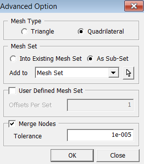
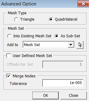
Mesh Type
Specify
an element type of extruded meshes.
Triangle
Generate
Triangular 2D meshes.
Quadrilateral
Generate Quadrilateral 2D meshes.
User Defined Mesh Set
User can specify the number of offsets per set. If one number has been entered, it will uniformly register generated mesh by the number of offsets. If more than one number has been entered, it will non-uniformly divide the Mesh Set by the given numbers. The sum of the numbers should not be greater than the total number of offsets.
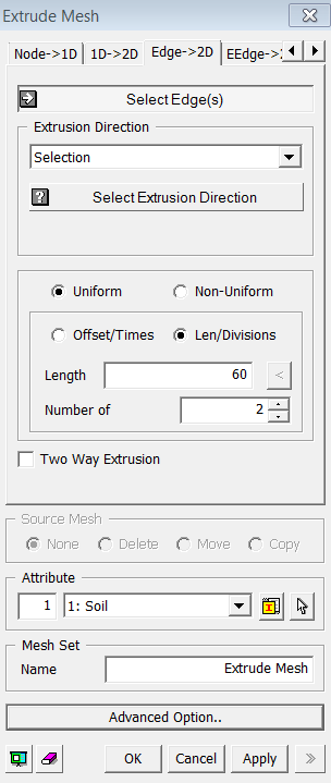
<Extrude Mesh : Edge->2D>
<Edge -> 2D>
Select Edge(s)
Select the Edges (Edge) that will be extruded.
Selection
Select
an extrusion direction (Datum Axis, Datum
Plane, Face, Edge).
Offset Component
Using
the vector components, the selected nodes are extruded at a uniform offset
interval by the number of times specified.
2 Point Vector
Select a direction of extrusion by a vector which is defined by two specified points. The coordinates of 2 points may be specified using Snap.
Extrude the selected elements at a uniform
distance by the number of times specified.
Offset
Enter
an offset distance for extrusion. If the selected direction has a finite
length, user can automatically input its length by pressing button.
Number of Times
Enter the number of offsets.
Extrude the selected nodes by specifying non-uniform distances entered as a function. Enter multiple distances separated by commas (,). For repetition, use the input format as the number of times @ distance. Example) 30,20,2@15,20
This option create the same mesh on the reverse side of specified direction.
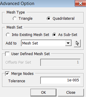
Specify an element type of extruded meshes.
Triangle
Generate
Triangular 2D meshes.
Quadrilateral
Generate Quadrilateral 2D meshes.
User Defined Mesh Set
User can specify the number of offsets per set. If one number has been entered, it will uniformly register generated mesh by the number of offsets. If more than one number has been entered, it will non-uniformly divide the Mesh Set by the given numbers. The sum of the numbers should not be greater than the total number of offsets.
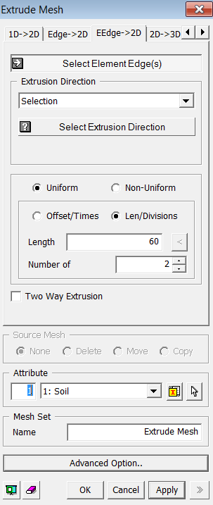
<EEdge -> 2D>
<EEdge ->2D>
Allows users to select an edge and extrude in the selected direction while controling the mesh length, offset/times, divisions
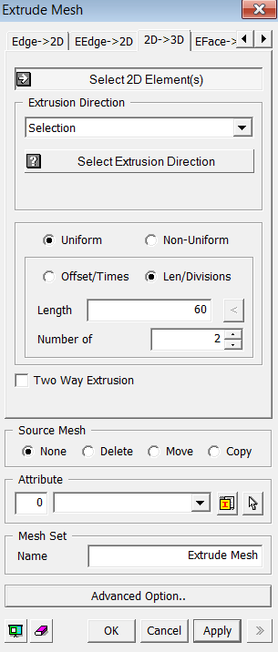
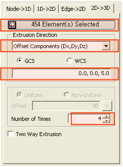
<Extrude Mesh : 2D->3D>
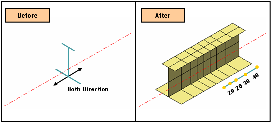
<2D -> 3D>: See its example
Select 2D Element(s)
Select the 2D elements (Mesh, Element) that will be extruded.
Selection
Select
an extrusion direction (Datum Axis, Datum
Plane, Face, Edge).
Offset Component
Using
the vector components, the selected nodes are extruded at a uniform offset
interval by the number of times specified.
2 Point Vector
Select a direction of extrusion by a vector which is defined by two specified points. The coordinates of 2 points may be specified using Snap.
Extrude the selected elements at a uniform
distance by the number of times specified.
Offset
Enter
an offset distance for extrusion. If the selected direction has a finite
length, user can automatically input its length by pressing button.
Number of Times
Enter the number of offsets.
Extrude the selected nodes by specifying non-uniform distances entered as a function. Enter multiple distances separated by commas (,). For repetition, use the input format as the number of times @ distance. Example) 30,20,2@15,20
This option create the same mesh on the reverse side of specified direction.
Specify what will be conducted to Source Meshes
after it has been extruded.
None
Leave
the Source Meshes as it is.
Delete
Delete
the Source Meshes.
Move
Move
the Source Mesh to the end of extrusion.
Copy
Leave the Source Meshes as it is and copy it to the end of extrusion.
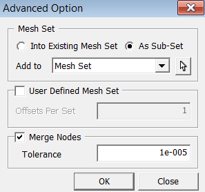
User Defined Mesh Set
User can specify the number of offsets per set. If one number has been entered, it will uniformly register generated mesh by the number of offsets. If more than one number has been entered, it will non-uniformly divide the Mesh Set by the given numbers. The sum of the numbers should not be greater than the total number of offsets.
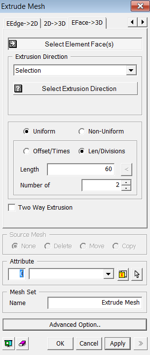
<Extrude Mesh : EFace->3D>
<EFace -> 3D>
Select Element Faces(s)
Select the element faces (Element Face) that will be extruded.
Selection
Select
an extrusion direction (Datum Axis, Datum
Plane, Face, Edge).
Offset Component
Using
the vector components, the selected nodes are extruded at a uniform offset
interval by the number of times specified.
2 Point Vector
Select a direction of extrusion by a vector which is defined by two specified points. The coordinates of 2 points may be specified using Snap.
Extrude the selected elements at a uniform
distance by the number of times specified.
Offset
Enter
an offset distance for extrusion. If the selected direction has a finite
length, user can automatically input its length by pressing button.
Number of Times
Enter the number of offsets.
Extrude the selected nodes by specifying non-uniform distances entered as a function. Enter multiple distances separated by commas (,). For repetition, use the input format as the number of times @ distance. Example) 30,20,2@15,20
This option create the same mesh on the reverse side of specified direction.
Specify what will be conducted to Source Meshes
after it has been extruded.
None
Leave
the Source Meshes as it is.
Delete
Delete
the Source Meshes.
Move
Move
the Source Mesh to the end of extrusion.
Copy
Leave the Source Meshes as it is and copy it to the end of extrusion.
User Defined Mesh Set
User can specify the number of offsets per set. If one number has been entered, it will uniformly register generated mesh by the number of offsets. If more than one number has been entered, it will non-uniformly divide the Mesh Set by the given numbers. The sum of the numbers should not be greater than the total number of offsets.
Notes
If the Source Elements are assigned with Plot Only element types, they would not be considered in analysis. Therefore, they are not necessary to be deleted after extrusion. However, if they are assigned something other than the Plot Only, they must be deleted so that they would not affect analysis result.