Protrude Mesh: Offset Mesh
![]()
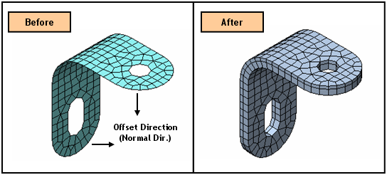
Function
Offset Mesh creates elements by offsetting a 1D element to a 2D element, a Edge to a 2D element, and a 2D element to a 3D element
Call
Mesh > Protrude Mesh > Offset
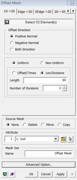
<Offset Mesh: 1D->2D Dialog Box>
<1D -> 2D>
Select 1D-Element(s)
Select the 1D elements (Mesh, Element) that will be offset
Offset Direction
Positive Normal
Define the offset direction by the positive normal direction of selected objects.
Negative Normal
Define the offset direction by the negative normal direction of the selected objects.
Both Direction
The selected objects will be offset by both the positive and negative directions.
Uniform
Offset the selected object at a uniform distance by the number of times specified.
Offset
Enter an offset distance.
Number of Times
Enter
the number of offsets.
Non-uniform Offset
Extrude the selected nodes by specifying non-uniform distances entered as a function. Enter multiple distances separated by commas (,). For repetition, use the input format as the number of times @ distance. Example) 30,20,2@15,20
Source Mesh
Specify what will be conducted to Source Meshes after it has been extruded.
None
Leave the Source Meshes as it is.
Delete
Delete the Source Meshes.
Move
Move the Source Mesh to the end of extrusion.
Copy
Leave
the Source Meshes as it is and copy it to the end of extrusion.
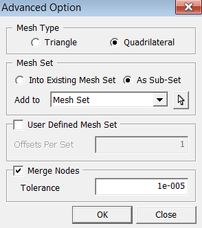
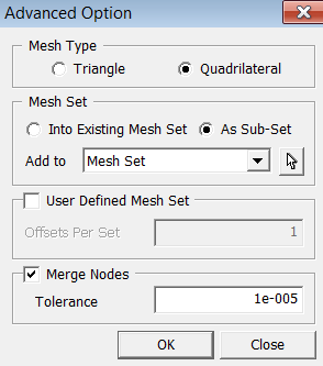
Mesh Type
Specify an element type of extruded meshes.
Triangle
Generate Triangular 2D meshes.
Quadrilateral
Generate
Quadrilateral 2D meshes.
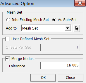
User Defined Mesh Set
User
can specify the number of offsets per set. If one number has been entered,
it will uniformly register generated mesh by the number of offsets. If
more than one number has been entered, it will non-uniformly divide the
Mesh Set by the given numbers. The sum of the numbers should not be greater
than the total number of offsets.
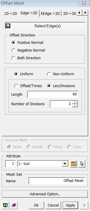
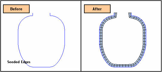
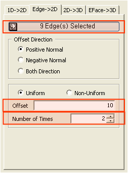
<Offset Mesh : Edge->2D Dialog Box>
<Edge -> 2D>: See its example
Select Edge(s)
Select the Edges (Edge) from generated mesh that will be offset.
Positive Normal
Define the offset direction by the positive normal direction of selected objects.
Negative Normal
Define the offset direction by the negative normal direction of the selected objects.
Both Direction
The selected objects will be offset by both the positive and negative directions.
Offset the selected object at a uniform distance by the number of times specified.
Offset
Enter an offset distance.
Number of Times
Enter the number of offsets.
Extrude the selected nodes by specifying non-uniform distances entered as a function. Enter multiple distances separated by commas (,). For repetition, use the input format as the number of times @ distance. Example) 30,20,2@15,20
Specify an element type of extruded meshes.
Triangle
Generate Triangular 2D meshes.
Quadrilateral
Generate Quadrilateral 2D meshes.
User Defined Mesh Set
User can specify the number of offsets per set. If one number has been entered, it will uniformly register generated mesh by the number of offsets. If more than one number has been entered, it will non-uniformly divide the Mesh Set by the given numbers. The sum of the numbers should not be greater than the total number of offsets.
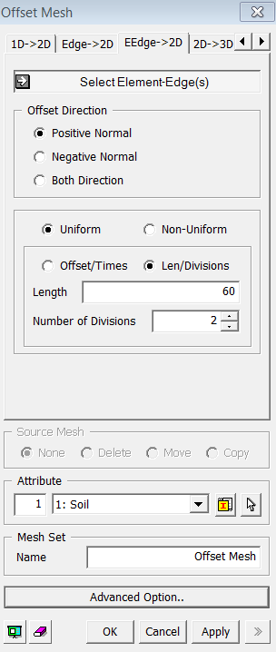
<EEdge ->2D>
<EEdge -> 2D>: See its example
Select Edge(s)
Select the Edges (Edge) that will be offset.
Positive Normal
Define the offset direction by the positive normal direction of selected objects.
Negative Normal
Define the offset direction by the negative normal direction of the selected objects.
Both Direction
The selected objects will be offset by both the positive and negative directions.
Offset the selected object at a uniform distance by the number of times specified.
Offset
Enter an offset distance.
Number of Times
Enter the number of offsets.
Extrude the selected nodes by specifying non-uniform distances entered as a function. Enter multiple distances separated by commas (,). For repetition, use the input format as the number of times @ distance. Example) 30,20,2@15,20
Specify an element type of extruded meshes.
Triangle
Generate Triangular 2D meshes.
Quadrilateral
Generate Quadrilateral 2D meshes.
User Defined Mesh Set
User can specify the number of offsets per set. If one number has been entered, it will uniformly register generated mesh by the number of offsets. If more than one number has been entered, it will non-uniformly divide the Mesh Set by the given numbers. The sum of the numbers should not be greater than the total number of offsets.
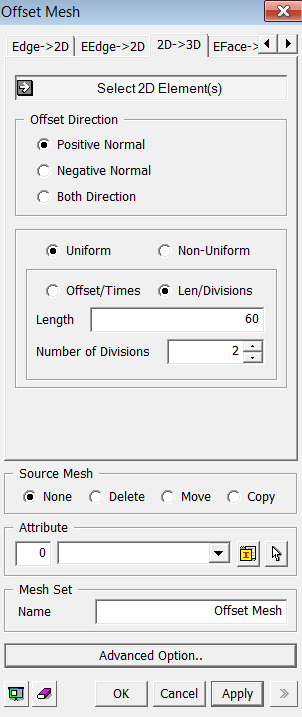
<Offset Mesh : 2D->3D Dialog Box>
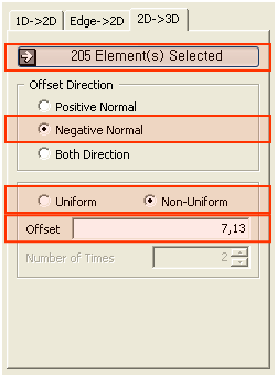
<2D -> 3D>: See its example
Select 2D Element(s)
Select the 2D elements (Mesh, Element) that will be offset.
Positive Normal
Define the offset direction by the positive normal direction of selected objects.
Negative Normal
Define the offset direction by the negative normal direction of the selected objects.
Both Direction
The selected objects will be offset by both the positive and negative directions.
Offset the selected object at a uniform distance by the number of times specified.
Offset
Enter an offset distance.
Number of Times
Enter the number of offsets.
Extrude the selected nodes by specifying non-uniform distances entered as a function. Enter multiple distances separated by commas (,). For repetition, use the input format as the number of times @ distance. Example) 30,20,2@15,20
Specify what will be conducted to Source Meshes after it has been extruded.
None
Leave the Source Meshes as it is.
Delete
Delete the Source Meshes.
Move
Move the Source Mesh to the end of extrusion.
Copy
Leave the Source Meshes as it is and copy it to the end of extrusion.
User Defined Mesh Set
User
can specify the number of offsets per set. If one number has been entered,
it will uniformly register generated mesh by the number of offsets. If
more than one number has been entered, it will non-uniformly divide the
Mesh Set by the given numbers. The sum of the numbers should not be greater
than the total number of offsets.
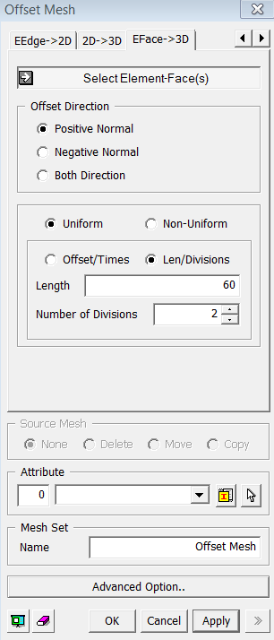
<Offset Mesh : EFace -> 3D Dialog Box>
<EFace -> 3D>
Select 2D Element(s)
Select the 2D quadrilateral elements (Mesh, Element) that will be offset.
Positive Normal
Define the offset direction by the positive normal direction of selected objects.
Negative Normal
Define the offset direction by the negative normal direction of the selected objects.
Both Direction
The selected objects will be offset by both the positive and negative directions.
Offset the selected object at a uniform distance by the number of times specified.
Offset
Enter an offset distance.
Number of Times
Enter the number of offsets.
Extrude the selected nodes by specifying non-uniform distances entered as a function. Enter multiple distances separated by commas (,). For repetition, use the input format as the number of times @ distance. Example) 30,20,2@15,20
User Defined Mesh Set
User
can specify the number of offsets per set. If one number has been entered,
it will uniformly register generated mesh by the number of offsets. If
more than one number has been entered, it will non-uniformly divide the
Mesh Set by the given numbers. The sum of the numbers should not be greater
than the total number of offsets.
.png) button to
assign
button to
assign