Protrude Mesh: Sweep
![]()
Function
Sweep Mesh creates elements by sweeping a node to a 1D element, a 1D element to a 2D element, a Edge to a 2D element, and a 2D element to a 3D element.
Call
Mesh > Protrude Mesh > Sweep incomplete beta
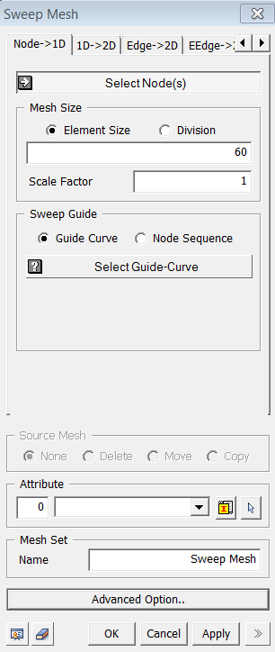
<Sweep Mesh : Node->1D>
<Node -> 1D>
Select Node(s)
Select the nodes (Mesh, Node) that will be swept.
<Common Features>
Mesh Size
Element Size
Specify the element size.
Division
Specify the number of divisions
of 3D mesh along the Guide Curve.
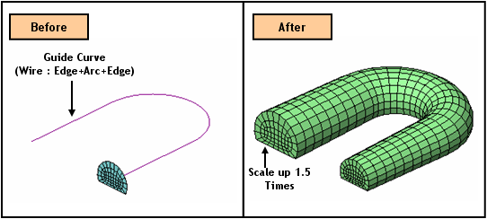
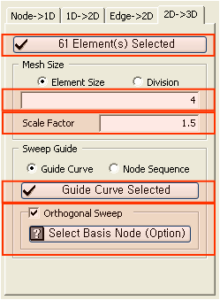
Scale Factor
Enter the scale factor
which will be applied for modifying element size during a Sweep operation.
Sweep Guide
Guide Curve
Select a Guide curve (Wire, Edge), which will be used for a
Sweep operation.
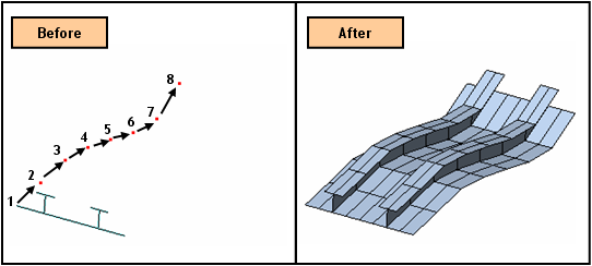
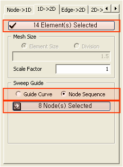
Node Sequence
Select nodes in a sequential
order by which a Sweep operation will be followed.
Source Mesh
Specify
what will be conducted to Source Meshes after it has been extruded.
None
Leave the Source Meshes
as it is.
Delete
Delete the Source Meshes.
Move
Move the Source Mesh to
the end of extrusion.
Copy
Leave the Source Meshes
as it is and copy it to the end of extrusion.
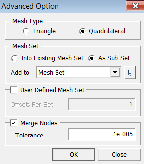
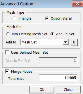
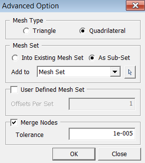
Mesh Type
Specify
an element type of extruded meshes.
Triangle
Generate Triangular 2D
meshes.
Rectangle
Generate Quadrilateral
2D meshes.
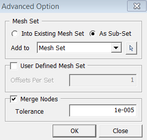
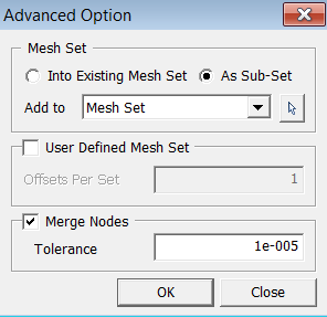
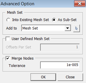
User Defined Mesh Set
User can specify the number
of offsets per set. If one number has been entered, it will uniformly
register generated mesh by the number of offsets. If more than one number
has been entered, it will non-uniformly divide the Mesh Set by the given
numbers. The sum of the numbers should not be greater than the total number
of offsets.
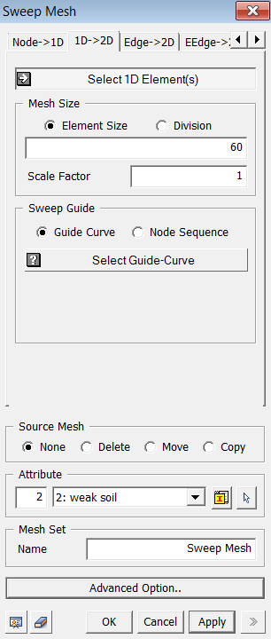
<Sweep Mesh : 1D->2D>
<1D -> 2D>
Select 1D-Element(s)
Select the 1D elements (Mesh, Element) that will be swept.
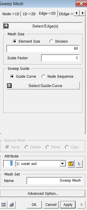
<Sweep Mesh : Edge->2D>
<Edge -> 2D>
Select Edge(s)
Select the Edges (Edge) that will be swept.
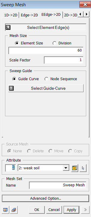
<EEdge -> 2D>
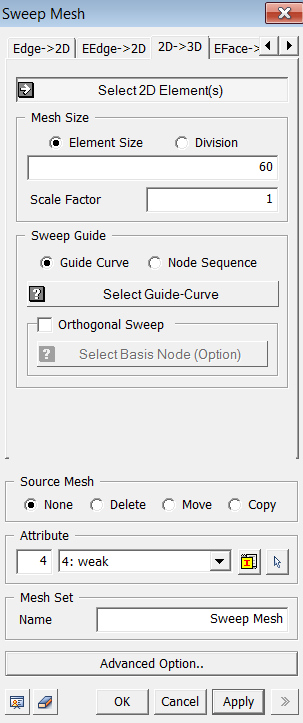
<Sweep Mesh : 2D->3D>
<2D -> 3D>
Select 2D-Element(s)
Select the 2D elements
(Mesh, Element)
that will be swept.
Orthogonal Sweep
The extruded cross section of the selected sweep 2D elements is orthogonal to the guide curve. The cross section of 2D elements is rotated to become orthogonal to the guide curve. User can define Base Node of sweep.
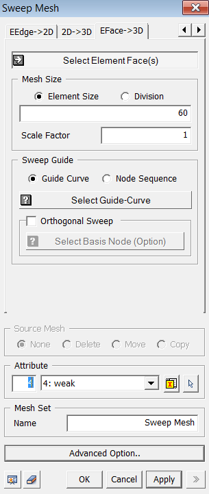
<Sweep Mesh :EFace->3D>
<Sweep Mesh : Eface->3D>
<EFace -> 3D>
Select Element Face(s)
Select the 2D elements (Mesh, Element)
that will be swept.
Orthogonal Sweep
The extruded cross section of the selected sweep 2D elements is orthogonal to the guide curve. The cross section of 2D elements is rotated to become orthogonal to the guide curve. User can define Base Node of sweep.
 to define