Size Control: Along Edge
![]()
Function
Edge Mesh Size sets a size for elements being created at selected edges.
Call
Mesh > Size Control > Along Edge
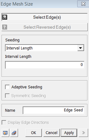
<Edge Mesh Size>
Select Edge(s)
Select
edges for which a mesh size will be specified.
Name
Enter
a name for the Edge Mesh Size Control.
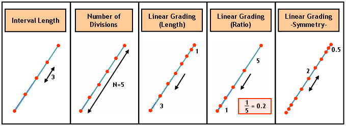
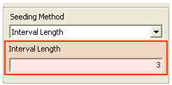
Seeding Method
Interval Length
Specify
the element size. See example.
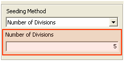
Number of Divisions
Specify
the number of elements to be created along the selected edges. See
example.
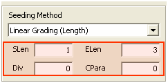
Linear Grading (Length)
The
spacing of dividing nodes is linearly controlled along the selected edges
by specifying the lengths of the start and end elements. See
example.
SLen
SLen stands for Start Length. Enter the element size (length) at the start points of the edges.
ELen
ELen stands for End Length. Enter the element size (length) at the end points of the edges.
Div
Div stands for Division. Enter the number of divisions along the selected edges. If 0 is entered, the program will appropriately divide the edges using the specified lengths. If the parameter is omitted, the program will set the divisions automatically.
CPara
CPara
stands for Concentration Parameter, which defines the range in which Linear
Grading will be applied. 0 represents the start
point, and 1 represents the end point. For example,
if 0.3 is entered, the selected edges are uniformly divided at the spacing
of SLen from the start points to the points of the
0.3 length ratio. Linear Grading is applied to
the remaining parts of the edges. If the ratio is negative, the parameter
will be applied from the end of the edge.
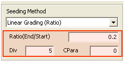
Linear Grading (Ratio)
The
spacing of dividing nodes is linearly controlled along the selected edges
by specifying the length ratio of the start and end elements. See
example.
Ratio
Enter
the ratio of the element size (length) at the start points of the edges
to the size at the end points.
Div
Enter
the number of divisions along the selected edges. Unlike Linear Grading
(Length), this parameter must be input.
CPara
CPara stands for Concentration Parameter, which defines the range in which Linear Grading will be applied. 0 represents the start point, and 1 represents the end point. For example, if 0.3 is entered, the selected edges are uniformly divided at the spacing computed from Div and Ratio from the start points to the points of the 0.3 length ratio. Linear Grading is applied to the remaining parts of the edges. If the ratio is negative, the parameter will be applied from the end of the edge.
Hyperbolic Tangent
Specifies the seeding location of node(s), which sets the size ratio of the start and end elements to a hyperbolic ratio.
S1
Enter the size of the element at the start point.
S2
Enter the size of the element at the end point. This seeding method can be selected when Symmetric Seeding is activated.
Div
Enter
the number of divisions along the selected edges.
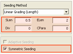
Adaptive Seeding
Automatically
increases the polynomial order so that the mesh can adjust to the needs
of the system.
Symmetric Seeding
Symmetric Seeding is applicable for Linear Grading. It applies Linear Grading Seeding from the start points to the midpoints of the selected edges. Symmetrical Seeding is applied to the remaining half parts about the midpoints. See example.
Notes
Once seeding is assigned to a shape, the seeding and the shape are interconnected. Since a shape with a seeding assignment can not be modified, a copy is made, which is then modified. Such interconnection can not be released by Freeze unlike other cross-references linked in the process of modeling. The seeding must be deleted in the Works Tree. It is therefore recommended that seeding be assigned at the last stage in a modeling process.
A size control, which has been created, is located under Size Control of Mesh in the Works Tree. It can be either edited or deleted by a right click on each entity. The assigned mesh size will continue to take effect until the Size Control is either edited or deleted in the Works Tree.