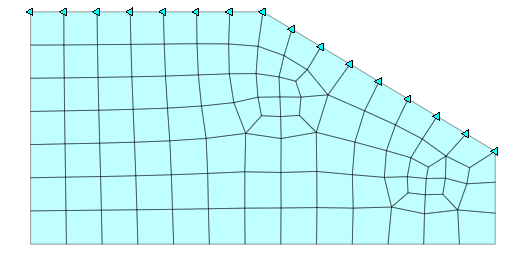
Boundary: Nodal Head
![]()
Function
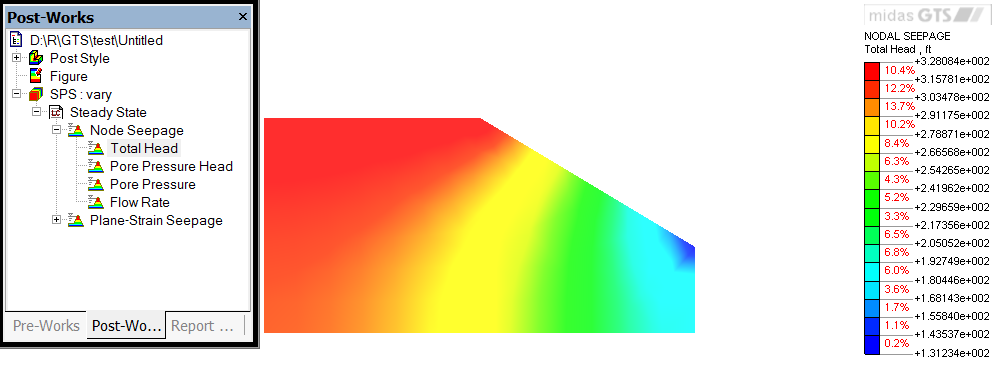
Assign nodal head. Nodal head value for both steady state and transient state can be defined using this function. For nodal head variation, please refer to the example below.
Call
Model > Boundary
> Nodal Head ![]()
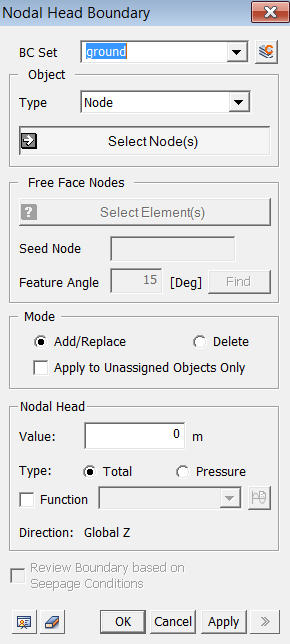
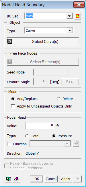
<Nodal Head Boundary>
BC Set
Select
a Boundary Set in which the specified boundary condition is included
Click ![]() to the right to prompt the Define Boundary Set dialog box to
add, modify or delete the Boundary Sets. If the user types the name of
the Boundary Set directly in the entry box, GTS will automatically create
the relevant Boundary Set.
to the right to prompt the Define Boundary Set dialog box to
add, modify or delete the Boundary Sets. If the user types the name of
the Boundary Set directly in the entry box, GTS will automatically create
the relevant Boundary Set.
Object
Type
Select
a method for selecting a part where the nodal head will be assigned.
Curve
Select Curves on which the boundary condition will be applied.
Surface
Select Surfaces on which the boundary condition will be applied.
Node
Select the nodes directly.
Free Face Node
Select the nodes on the free faces of the selected
element. All nodes within the defined angle (Feature Angle) from a seed
node will be assigned.
Free Face Node
It
becomes active when selecting Free Face Node selection method is designated.
Seed Node
Select a Seed Node which becomes the reference of determining free face.
Feature Angle
When
it expands out the free face selection from the Seed Node, it only select
element nodes within the specified Feature Angle.
Click
 to select free face nodes and they will appear on the screen.
Mode
Add
Add/Modify nodal head value on selected nodes.
Delete
Delete nodal head value on selected nodes.
Apply to Unassigned Objects Only
When
adding new nodal head value, this option applies nodal head value only
to the unassigned nodes.
Nodal Head
Nodel Head values are referenced with respect to the GCS
Value
Enter the nodal head value.
Type
Select a type of nodal head. Two options are provided - Total Head and Pressure Head.
Function
If
the nodal head is defined using a function, select the relevant function.
If the nodal head has not been created yet, click ![]() button to invoke the Create/Modify Function dialog box.
button to invoke the Create/Modify Function dialog box.
Review Boundary based on Seepage Conditions
This option enables the user to check nodal head condition as the water level changes in the analysis model.