|
BC
Set
Select
a Boundary Set in which the specified boundary condition is included
Click  to the right
to prompt the Define Boundary Set dialog box to add, modify or delete
Boundary Sets. If the user types the name of the Boundary Set directly
in the entry box, GTS will automatically create the relevant Boundary
Set. to the right
to prompt the Define Boundary Set dialog box to add, modify or delete
Boundary Sets. If the user types the name of the Boundary Set directly
in the entry box, GTS will automatically create the relevant Boundary
Set.
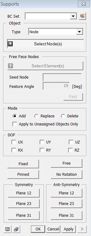
Type
Face
Flux
Apply surface flux value on planar elements
or face of solid elements.
Edge Flux
Apply surface flux value on line elements
or edge of planar elements.
Object
Type
Select
a method for selecting nodes where the Surface flux will be assigned.
Surface
Select
Surface on which the boundary condition will be applied.
Free Face Element
Select
free face of solid elements.
Curve
Select
Curves on which the boundary condition will be applied.
Free Edge Element
Select
free edge of planar elements.
Free
Face Node
It becomes active when the Free Face Node selection
method is designated.
Seed
Node
Select a Seed Node which becomes the reference
for determining the free face.
Feature Angle
After expanding the free face selection from
the Seed Node, it only selects element nodes within the specified Feature
Angle.
Click to select the free
face nodes, and they will appear on the screen.
Mode
Add
Add new restraints to the selected nodes
Replace
Replace the previously defined restraints on
the selected nodes
Delete
When adding new restraints, this option applies
restraints only to the unassigned nodes.
Apply to Unassigned Objects Only
When
adding a new surface flux value, this option applies nodal head value
only to the unassigned nodes.
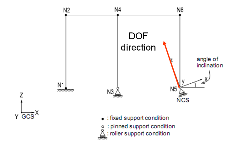
DOF
UX, UY, UZ
Displacement
degree-of-freedom in the Global Coordinate Axes.
RX, RY,RZ
Rotational
degree-of-freedom in the Global Coordinate Axes.
The following buttons simplify the individual
data entries described above.
Fixed: Restrain all DOFs.
Free: Unrestrain all DOFs.
Pinned: Restrain only displacement DOFs.
No Rotation
: Restrain only rotational DOFs.
Symmetry
More
prescribed restrains can be specified using the following symmetric conditions.
Plane12: Restrain nodes symmetric about
the Global X-Y plane.
Plane23: Restrain nodes symmetric about
the Global Y-Z plane.
Plane31: Restrain nodes symmetric about
the Global X-Z plane.
Anti-Symmetry
More
prescribed restrains can be specified using the following anti-symmetric
conditions.
Plane12: Restrain nodes anti-symmetric
about the Global X-Y plane.
Plane23: Restrain nodes anti-symmetric
about the Global Y-Z plane.
Plane31: Restrain nodes anti-symmetric
about the Global X-Z plane. |