Element: Create Interface
![]()
Function
Create interface elements which enables sliding and separation between elements.
Call
Model > Element > Create Interface
<Create Interface>
<Create Interface- From Plate Method>
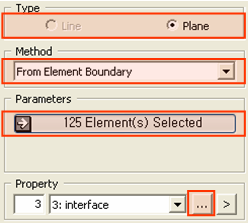
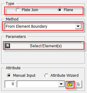
Type
2D
Create 1D interface elements for 2D elements.
Plane
Create
2D plane interface elements between 3D elements.
Method
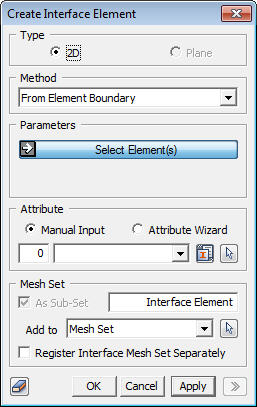
<From Element Boundary> ----------> Goto Example
-----------------------------------------------------------------------------------------------------------------------------------------
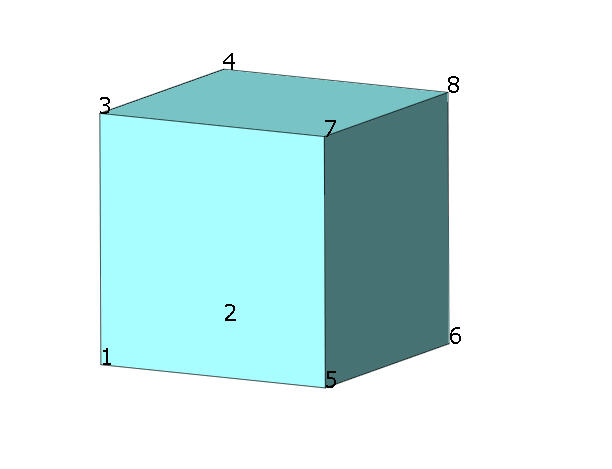
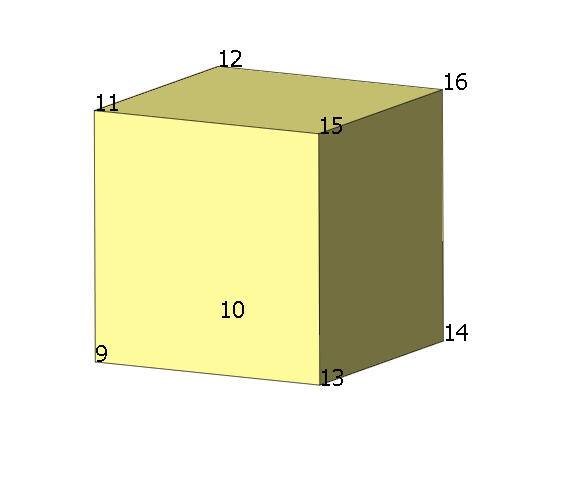
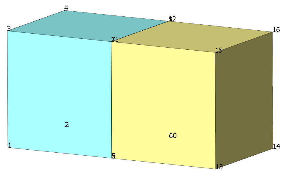
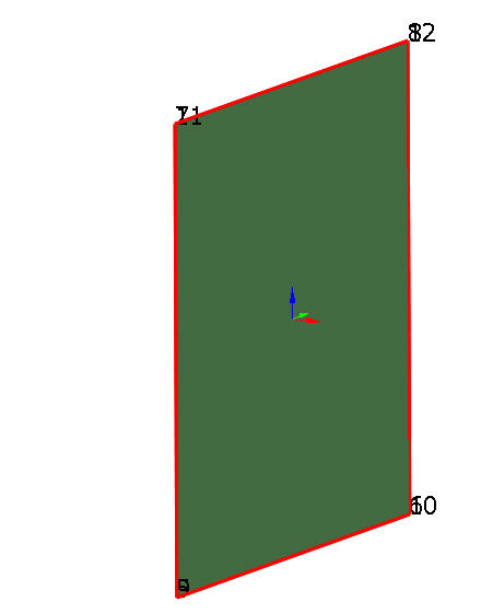
(Example)
-----------------------------------------------------------------------------------------------------------------------------------------
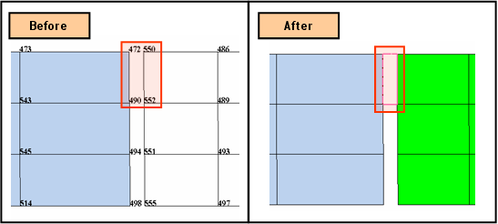
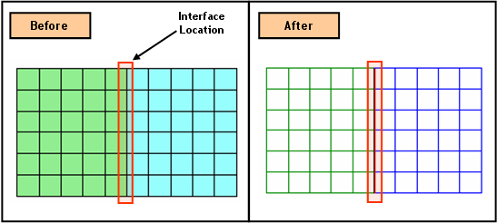
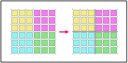
Create interface elements between the boundary of selected elements and neighboring element faces.
Select Element
Select
elements or mesh sets for creating interface elements.
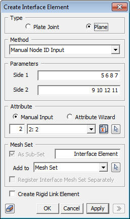
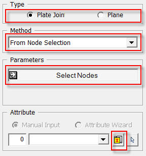
<Manual Node ID Input> ----------> Goto Example
-------------------------------------------------------------------------------------------------------------------------------------------
(Example)
-------------------------------------------------------------------------------------------------------------------------------------------
Create interface elements by entering node ID directly. The topology of generated interface element is depending on the number of nodes selected in Side 1 and Side 2.
<2D>
No.
of Nodes : 2 for each -> First order interface element of a line type
No. of Nodes : 3 for each -> Second order interface element of a line
type
<3D>
No.
of Nodes : 3 for each -> First order interface element of a triangular
type
No. of Nodes : 4 for each -> First order interface element of a rectangular
type
No. of Nodes : 6 for each -> Second order interface element of
a triangular type
No. of Nodes : 8 for each -> Second order interface element of a rectangular
type
Side 1
Enter
node ID of a side of an interface element.
Side 2
Enter node ID of an opposite side of "Side 1".
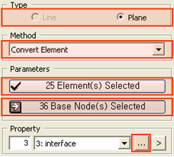
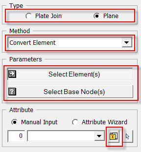
<Convert Element> ----------> Goto Example
-------------------------------------------------------------------------------------------------------------------------------------------
(Example)
-------------------------------------------------------------------------------------------------------------------------------------------
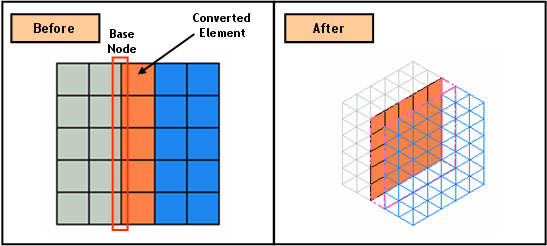
Convert 1D, 2D, 3D elements to interface element of relevant type. By selecting just elements, it would not provide enough information to define the orientation of interface elements. Therefore, it is required to specify Base Nodes.
Select Element(s)
Select
elements to convert to interface elements.
Select Base Node(s)
Select
nodes which determines the element's orientation.
-------------------------------------------------------------------------------------------------------------------------------------------
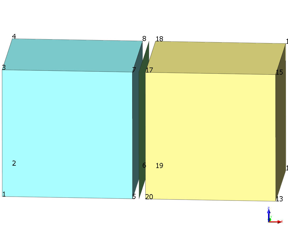
(Example)
-------------------------------------------------------------------------------------------------------------------------------------------
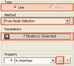
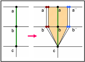
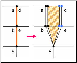
Create interface elements between elements by selecting connecting nodes. For 3D mode, it is recommended to define Branch Nodes if it does not generate interface element properly.
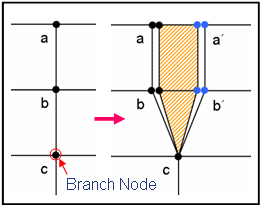
Select Node(s)
Select
node to create interface elements.
Select Branch Node(s)
Select
nodes which will be located at the root of interface elements.
-------------------------------------------------------------------------------------------------------------------------------------------
(Example)
-------------------------------------------------------------------------------------------------------------------------------------------
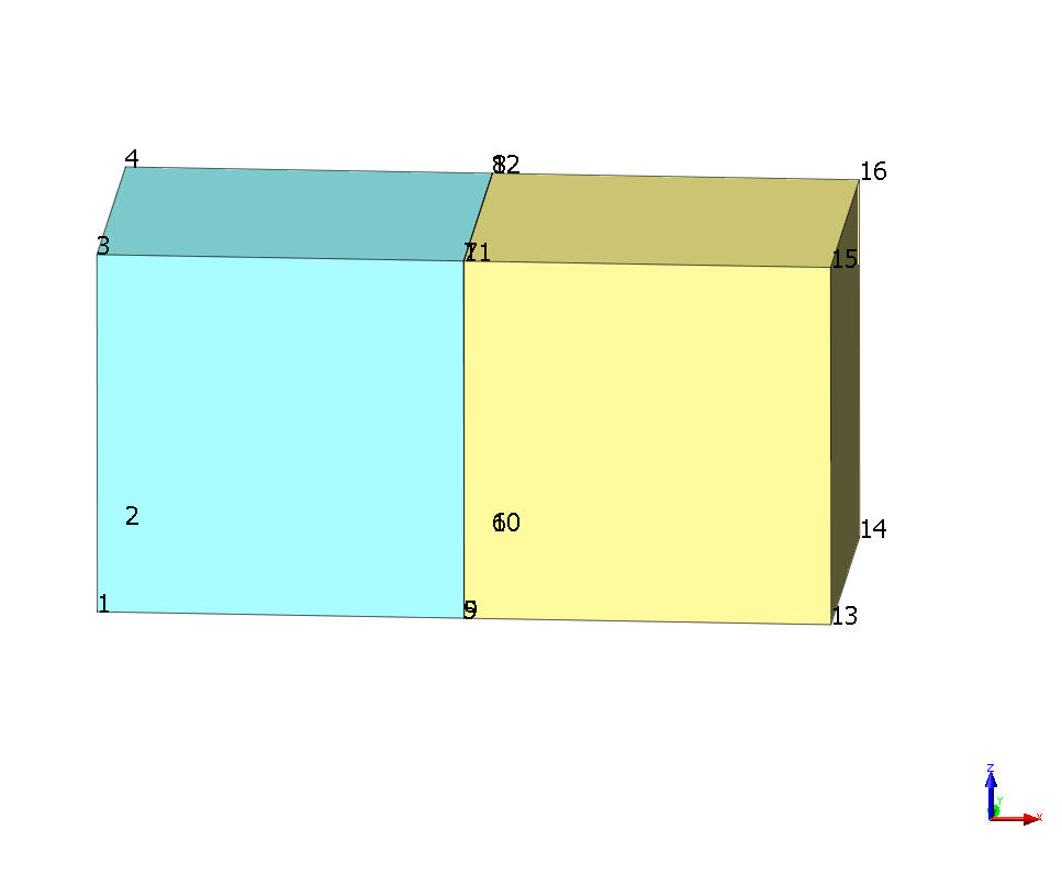
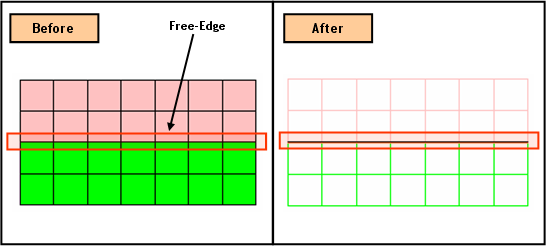
Create interface elements by selecting free faces/edges. Interface elements are generated between free faces/edges which are facing each other. Therefore, both sides of free faces/edges must be selected.
Select Element-Face(s)/Edge(s)
Select
free faces/edges of elements to create interface elements.
Tolerance
Specify
a tolerance for the distance allowance between facing free face/edges.
-------------------------------------------------------------------------------------------------------------------------------------------
(Example)
-------------------------------------------------------------------------------------------------------------------------------------------
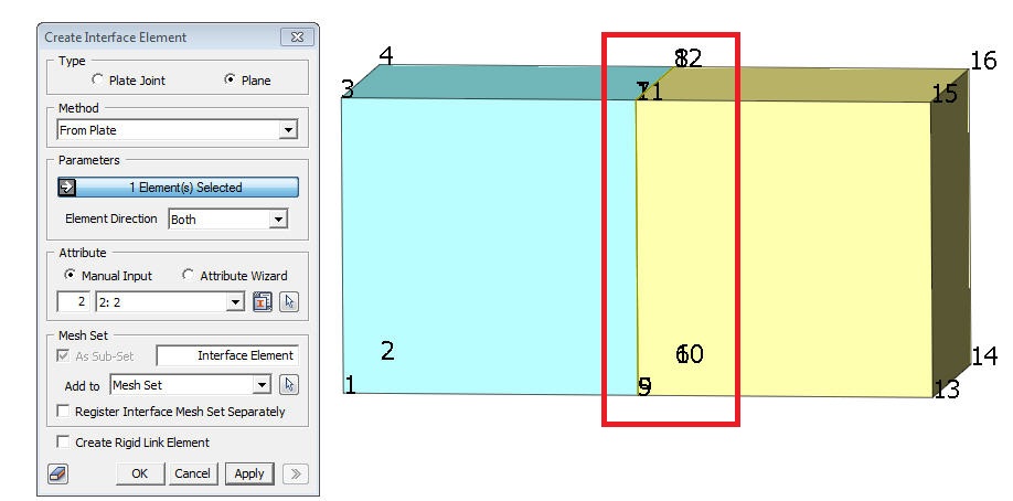
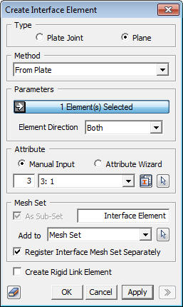
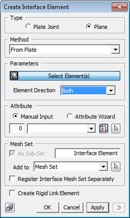
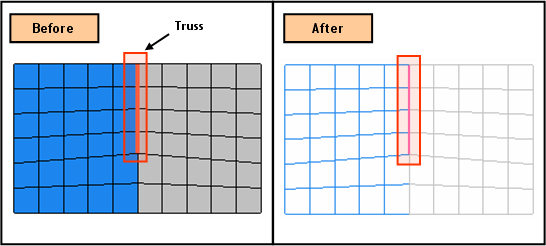
Create interface elements on both sides of selected plate(3D) / truss(2D) / beam(2D). Selected elements must be located between 3D or 2D elements accordingly.
Select Elements(s)
In the case of 3D, Select Plate element (2D Element) to create interface elements on both sides.
In the case of 2D, Select Truss/Beam element (1D Element) to create interface elements on both sides.
Element Direction
Both : Creates two interface elements
Normal : Creates one interface element
Neg-Normal : Creates one interface element with inverse element coordinate system
Define the coordinate system of 0D Interface Elements.
Register Interface Mesh Set Separately
If Element Direction"Both" is selected, the mesh sets can be defined independently by selecting this option.
Create Rigid Link Element
Create rigid links between interface elements.
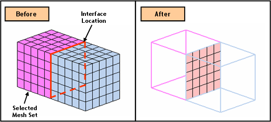
<From Mesh Set (T/X-cross type)>
This option is only available when Type is either 2D or Plate Joint. The feature create interface elements between boundaries of selected Mesh Set. It is also capable to create in T or X section.
Select Mesh Sets
Select Mesh Sets which becomes the boundary for interface elements.
<Manual Input>
Users can manually enter interface element properties.
<Attribute Wizard>
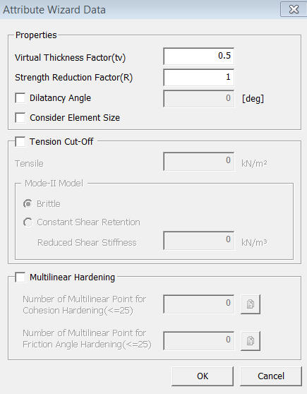
The Attribute Wizard automatically calculates the property of interface element.
<Properties>
Virtual Thickness Factor (tv) : This parameter is used to derive the interface elastic stiffness from the soil stiffness. Interface stiffness must be large enough to produce negligible relative displacements before plastic slip or tensile debonding occurs. However, increase in interface stiffness value compared to the surrounding soils stiffness can result in numerical instability in the analysis. The wizard estimates the associated interface stiffness (N/m3) that would be equivalent to the stiffness of a soil column of a width equal to the specified virtual thickness. It is therefore advised to specify a virtual thickness that is about 10 times smaller than the average element size of the soil in the considered region.
Strength Reduction Factor (R) :This parameter is used to derive the cohesion and friction angle of the interface elements from the strength properties of the soil (See Figure 1.4.2). The interface strength parameters are equal to the neighboring soil strength parameters if R=1. For the interface between soil and a smooth structural element (steel or precast concrete) it is generally assumed that the reduction factor is in the order of 0.65. For the interface between soil and cast in place concrete, the reduction factor may be as high as 1.
Dilatancy Angle : Enter the Dilatancy Angle of boundary element
Consider Element Size : Consider the Element Size in the calculation for stiffness
<Tension Cut-Off> <Multilinear Hardening> The user can assign the reference parameters.
Notes
1) The user should assign the Interface Attribute correctly to generate the Interface Element. In the case of inserting only Attribute ID, the generation of Interface Element might be failed.
2) Parameters for manual input (Normal Stiffness Modulus, Shear Stiffness Modulus) are automatically calculated by using the following formulae.
Normal Stiffness Modulus (Kn) = elastic modulus of ground (E) X 10 / (Ie (element size) X virtual thickness factor)
Shear Stiffness Modulus (Kt) = elastic modulus of ground (normal value) / (Ie (element size) X virtual thickness factor)
Note: The default value for element size (Ie) has been set to 1.0 m.
 to define Property.