Load: Line Beam Load
![]()
Function
Where several beam elements are continuously connected in a straight line, set the end points of the line and enter the continuous beam load. The load type may be a distributed load or in-span concentrated load. Modify or delete previously entered loads as necessary. Loads can be also applied to a curved continuous beam which is located in the plane of the loading direction. In addition, curvilinear distribution such as earth pressure can be loaded by using curved loads.
Call
Model > Load > Line Beam Load ![]()
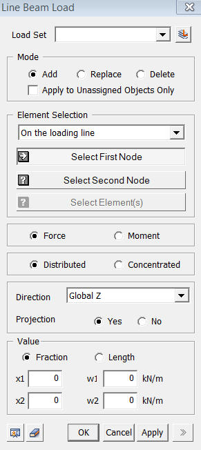
<Line Beam Load>
Load Set
Select
a Load Set in which the specified load is included
Click .jpg) to the right to prompt the Define Load Set dialog box to add,
modify or delete the Load Set. If the user types the name of Load Set
directly in the entry box, GTS will automatically create the relevant
Load Set.
to the right to prompt the Define Load Set dialog box to add,
modify or delete the Load Set. If the user types the name of Load Set
directly in the entry box, GTS will automatically create the relevant
Load Set.
Mode
Add
Add new loads to the selected nodes
Replace
Replace previously defined loads on the selected nodes
Delete
Delete previously defined loads on the selected nodes
Apply to Unassigned Objects Only
When
adding new loads, this option applies loads only to the unassigned nodes.
Element Selection
Select
the control target for loading the beam loads.
On the loading Line
Line Beam Loads are applied to the elements on a straight line defined by two nodes.
Select Element
Line
Beam Loads are applied to the selected elements.
Force / Moment
Determine
whether the load is either a force or a moment.
Distributed / Concentrated
Determine
whether the load is concentrated or uniformly distributed.
Direction
Assign
the loading direction of continuous beam loads. The loading directions
are as follows.
Local x
Beam load applied in the local x-direction of the element.
Local y
Beam load applied in the local y-direction of the element.
Local z
Beam load applied in the local z-direction of the element.
Global X
Beam load applied in the GCS X-direction
Global Y
Beam load applied in the GCS Y-direction
Global Z
Beam
load applied in the GCS Z-direction
Projection
Define
if the continuous beam load is to be applied along the continuous beams
or if the loading is to be vertically projected on the beams. This command
takes effect only when the load type is 'Uniform Loads' or 'Trapezoidal
Loads' and the loading direction is 'Global'.
Yes
When a vertically projected continuous beam load is applied to the continuous beams.
No
When
a continuous beam load is applied along the continuous beams.
Value
Define if the loading positions of the continuous beam loads are to be entered as a relative ratio of a loaded beam length or as the actual beam length.
Fraction
Relative ratio of a beam length.
Length
Actual beam length.
x1
Enter the start point of the line beam load.
x2
Enter the end point of the line beam load.
w1
Enter
the value of the line beam load at the start point.
w20
Enter
the value of the line beam load at the end point.
Copy Load
Check
in Copy Load to repeat the continuous beam loads for other rows of continuous
beams
Axis
Set
the copy direction
x
GCS
x-direction
y
GCS
y-direction
z
GCS
z-direction
Distances
Enter the distances along which the loads are to be copied. When copying loads onto several other rows of continuous beams, enter the copy distances (or spacings) as many times as required. (For example: 5.0, 3.0, 4.5, 3@5.0)