Load: Time History Load Set
![]()
Function
Define the conditions and required control data for time history analysis.
Call
Model > Load > Time History Analysis Data > Time History Load Set

<Time History Load Set dialog box>
.jpg)
To enter new or additional time history analysis
load sets.

To
modify previously entered time history analysis load sets.
.jpg)
To delete previously entered time history analysis load sets.
Click
or
to display the dialog box below and enter the required data in the relevant
entry fields.

<Add/Modify Time History Load Set>
Load Set Name
Enter the name of the time history analysis load
set.
Description
State a brief description related to the time history
load set.
Analysis Type
Linear
Linear
Time History Analysis
Analysis Method
Modal
Modal
Superposition Method
Direct Integration
Direct
Integration Method
Time History Type
Transient
Time
history analysis is carried out on the basis of loading a time load function
only once. This is a common type for time history analysis of earthquake
loads.
Periodic
Time
history analysis on the basis of repeatedly loading a time load function,
which has a period identical to the End Time. This type is applicable
for machine vibration loads.
End Time
End Time is the time until
which the time history analysis is required [in seconds].
Time Increment
Time Increment of a time history analysis significantly
affects the accuracy of the analysis results. A common rule of thumb for
determining the time increment is to use at least 1/10 of the smaller
of the period of the time forcing function or the natural frequency of
the structure [in seconds].
Step Number Increment for Output
Analysis time step required for producing results
of the time history analysis.
Damping
Direct Modal
The
user defines the damping ratio for each mode, and the modal response will
be calculated based on the user-defined damping ratios. Direct Modal can
be used in the Modal Analysis Method and Direct Integration Method.
Direct Specification of Modal Damping
Directly specify the damping ratio for each mode.
Damping Ratio for All Modes
It applies to all modes except those which have directly specified by the user in the modal damping ratios. It applies to all the modes other than the damping ratios assigned to specific modes in the Modal Damping Overrides table below. In a modal analysis, if the entered damping ratio is different from the user-defined damping ratio in Response Spectrum Functions, the previous spectrum data will be adjusted and used in the analysis based on this damping ratio.
Modal Damping Overrides
The
user directly defines the damping ratios by modes.
Mode
Mode Number
Damping Ratio
Damping Ratio
Mass and Stiffness Proportional
Damping
coefficients are computed for mass proportional damping and stiffness
proportional damping.
Damping Type
Check whether or not the damping matrix type is
proportional to mass and/or stiffness.
Direct Specification
Enter the damping coefficients for the Damping Types that are checked on.
Calculate from Modal Damping
The proportional coefficients are calculated from
the user-defined modal damping ratios and automatically entered.
Coefficients Calculation
Depending on the checked Type of Proportional Damping,
one modal damping coefficient can be defined if it is proportional to
either mass or stiffness, and two modal damping coefficients can be defined
if it is proportional to both.
Frequency [Hz]
Specify modal frequencies for which the damping ratios will be defined, which will be used to calculate the proportional coefficients.
Period [Sec]
Specify modal periods for which the damping ratios will be defined, which will be used to calculate the proportional coefficients.
Damping Ratio
Specify the damping ratios corresponding to the
specified Frequencies or Periods.
 : Damping Ratio calculator dialog box is activated,
which calculates and shows the modal damping ratio having a specific frequency
or period, from the entered proportional coefficients. Damping ratios
are defined for a maximum of two modes when damping proportional to mass
and stiffness is used. This function makes it possible to calculate the
magnitudes of damping ratios for the other modes.
: Damping Ratio calculator dialog box is activated,
which calculates and shows the modal damping ratio having a specific frequency
or period, from the entered proportional coefficients. Damping ratios
are defined for a maximum of two modes when damping proportional to mass
and stiffness is used. This function makes it possible to calculate the
magnitudes of damping ratios for the other modes.
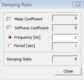
<Ratio Dialog Box>